Description and operation
The changed position of the seat by memorizing into the power seat unit with IMS switch controlling the optimal seat position set by the driver can be restored with the IMS switch.
It has the function of prohibiting the restoring action during driving and emergent stopping the linked motion for safety.
The main functions are as follows.
| 1. | Manual operation: Motor control with the seat manual switch | (1) | The position of the seat is changed by operating the motor when the signal is input with manual switch for the seat (Slide, recline, front tilt, rear height adjusting) |
|
| 2. | Memory function : Available for memorizing/reproducing the data for two persons with IMS switch. | (1) | The memorized motion (seat and outside mirrors) for the optimal seal position set by the driver based on the CAN data (IMS→DDM) with IMS switch. |
| (2) | Reproduction by the CAN data received from IMS switch controlling. |
|
| 3. | Motion linked for getting on/off | (1) | Function of getting on/off linked motion depending on the state of ON/OFF the engine |
| (2) | Use of IMS CAN data communcation |
| (3) | Condition for operating getting on : When the electric power is in ACC |
| (4) | Condition for operating getting off: When the engine is OFF |
|
| 4. | Memorization and Recall of Mirror Position Using Memory Switch | (1) | System Description | –
| IMS switch inputs are received by Power Seat Module (PSM). |
| –
| Receiving the IMS switch inputs, the PSM will send the information to DDM and ADM via CAN communication. |
| –
| Receiving the information from the PSM, the DDM and the ADM will memorize and recall it. |
|
| (2) | They carry out the memorization and recall operation if the following conditions are met : | –
| Gear selected in P (Park) position |
| –
| The vehicle speed is "0 km/h" according to the information transmitted from the BCM via CAN communication. |
|
| (3) | Save Mirror Position | –
| Move the mirrors on the sides of driver and passenger seats to desired positions. |
| –
| Press the SET switch from IMS switches. |
| –
| Press the switch 1 or 2 within the limited time period. |
| –
| The mirror positions will be stored in the IMS switch 1 or 2 of the DDM and the ADM. |
|
|
Reproducing Motion
| 1. | The buzzer is operated once and adjusted automatically to the memorized position when the CAN data is received from IMS. |
| 2. | The CAN data which is not memorized do not operate for reproduction. |
| 3. | The finally received CAN data for reproduction shall be preferred when other CAN data is received during reproduction motion. |
| 4. | The seat stops the reproduction when reproducting CAN data is received by pressing button 1 or 2 during reproduction. |
| 5. | The seat stops the reproducing when the memorized CAN data is received by pressing SET button during reproduction. | •
| Press the SET button once more to store the position of stop. |
|
|
| 6. | Automatic stop when seat is virtual limit position during reproduction. |
| 7. | Do not operate the motor when the difference between the memorized position for reproduction and current position is less than 4 pulses. |
Conditions for Prohibiting the Reproduction
Prohibit the reproduction in case of falling on any of following conditions and stop controlling during reproduction action.
| 1. | IGN2 OFF (Excluding within 30 seconds after door opening or closing.) |
| 2. | Higher than 3km/h of vehicle speed |
| 3. | When the switch is controlled manually |
| 4. | Operation time chart 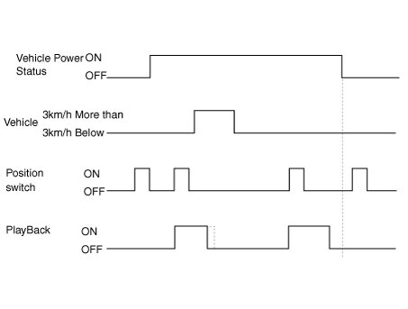
|
Decision On the Operation Priority
| 1. | The motor operation shall be delayed for 100±10msec for preventing the overlapping of inrush circuit during motor start and the priority at this case shall be as follows. Slide > Backrest adjustment >Front height adjustment >Rear height adjustment Operation time chart 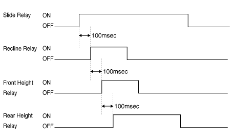
|
Operation Linked with Getting On/getting Off
| 1. | Returning motion to backwards during getting off and to forwards during getting on (Corresponding to slide only) |
| 2. | Starting of operation when the engine is off. |
| 3. | Moving to the targeted positionof ACC ON |
| 4. | Behavior prohibited conditions | –
| Power seats, if the operation of the manual control switch. |
| –
| Driver Settings menu (USM) is Off, |
| –
| Passenger action on receipt of the play command |
|
Virtual Limit
| 1. | Virtual Limit Setting Conditions and Positions Set an arbitrary virtual limit using any methods below since there is no independent limit switch, restricting driving of slide, backrest, and front / rear height adjusting motors : | (1) | Slide recall: When there is no slide motor pulse inputted (mechanical end stop) through 6 or more pulses for 2 seconds during any operation triggered by a manual switch and memory recall operation, stop the motor immediately and set a position ahead of 6 pulses away from the position as the limit position in the driving direction (same for the opposite limit setting).
Set position
| Virtual Limit Setting Conditions
| Virtual Limit Setting Positions
| Slide
| 2 seconds, 6 pulses
| 6 pulses from restricted position
| Backrest adjustment (recline)
| 2 seconds, 155 pulses
| 155 pulses from restricted position
| Front tilt
| 1 second, 6 pulses
| 6 pulses from restricted position
| Rear height adjustment
| 1.5 seconds, 6 pulses
| 6 pulses from restricted position
|
※ Pulse : A waveform unit to measure revolution of a motor |
| (2) | Once a virtual limit has been set, do not perform any memory recall operation to a position out of the limit range, in order to prevent motor damage due to kinematic locking. |
| (3) | Renew the limit position if a pulse is normally inputted out of that position by memory manipulation with the limit set. |
|
| 2. | Virtual Limit Setting Procedure | (1) | Slide : To set a virtual limit, move a seat forwards to the end stop, hold it for 2 seconds, move it rearwards to the end, and then hold it for 2 seconds. |
| (2) | Backrest adjustment (recline) : To set a virtual limit, move a backrest forwards to the end stop, hold it for 2 seconds, move it rearwards to the end, and then hold it for 2 seconds. |
| (3) | Front tilt : To set a virtual limit, move a seat upwards to the end stop, hold it for 1 second, move it downwards to the end, and then hold it for 1 second. |
| (4) | Rear height adjustment : To set a virtual limit, move a seat upwards to the end stop, hold it for 1.5 seconds, move it downwards to the end, and then hold it for 1.5 seconds. |
|
Components and components location
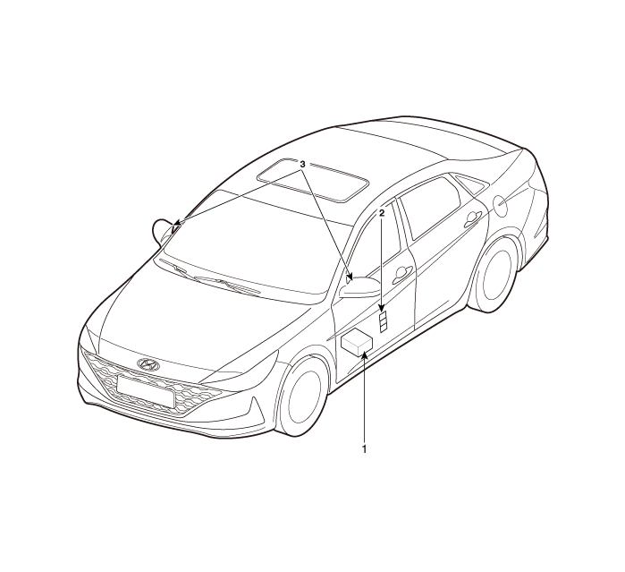
1. Memory power seat unit (PSM)
2. IMS control switch
| 3. Outside Mirror
|
Specifications
[Memory Power Seat Unit ]
Item
|
Specifications
|
Rated voltage
| DC 12V
|
Operating Voltage
| DC 9V - 16V
|
Operating Temperature Range
| -30°C to 75°C
|
Dark current
| Max. 1㎃
|
[Memory Power Seat Switch ]
Item
|
Specifications
|
Rated voltage
| DC 5V
|
Type
| Soft Feeling Tact type
|
Operating Temperature Range
| -30°C to 80°C
|
Schematic diagrams
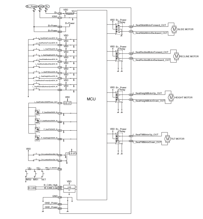
Memory power seat unit
Components and components location
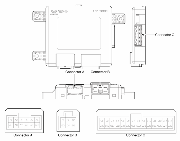
Connector Pin Information
Pin no
|
Connector A
|
Connector B
|
Connector C
|
1
| -
| B (+)
| Slide switch signal (Forward)
|
2
| Reclining motor (Forward)
| GND(Power)
| Reclining switch signal (Forward)
|
3
| Height motor (Up)
| B (+)
| Front tilt switch signal (Up)
|
4
| Slide motor (Forward)
| -
| Height switch (Up)
|
5
| -
| GND
| Reclining limit switch signal (Forward)
|
6
| Reclining motor (Backward)
|
| B_CAN (High)
|
7
| Tilt motor (Up)
| B_CAN (Low)
|
8
| Tilt motor (Down)
| -
|
9
| Height motor (Down)
| Driver lumber motor (Mid)
|
10
| Slide motor (Backward)
| Seat slide sensor
|
11
|
| Seat tilt sensor
|
12
| -
|
13
| Seat position sensor power
|
14
| IGN 1
|
15
| Seat slide switch (Backward)
|
16
| Seat recline switch (Backward)
|
17
| Tilt switch (Down)
|
18
| Height switch (Down)
|
19
| Reclining limit switch signal (Backward)
|
20
| GND
|
21
| -
|
22
| IMS Switch
|
23
| Driver lumber motor (Def)
|
24
| Reclining sensor
|
25
| Height sensor
|
26
| -
|
27
| -
|
28
| B(+)
|
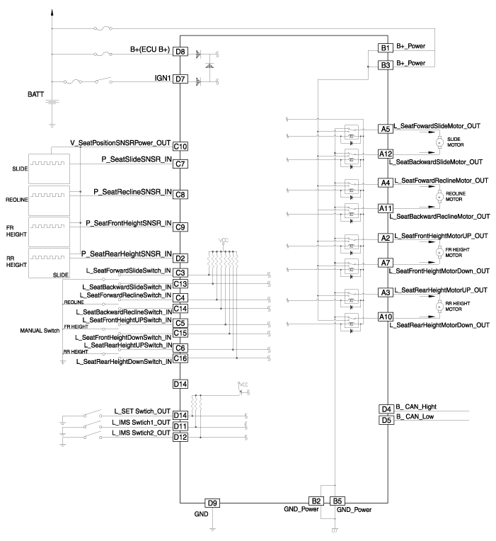
Schematic diagrams
Repair procedures
| 1. | Disconnect the negative (-) battery terminal. |
| 2. | Remove the driver seat assembly. (Refer to Body - "Front Seat Assembly") |
| 3. | Loosening the IMS unit mounting screws. 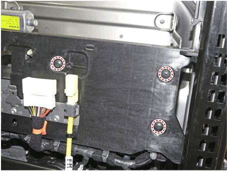
|
| 4. | Disconnect IMS module connectors (A) and then remove the IMS unit. 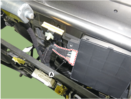
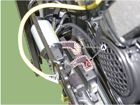
|
| 1. | Install the memory power seat unit. |
| 2. | Install the driver seat assembly. |
| 3. | Connect the negative (-) battery terminal. |
Memory power seat switch
Components and components location
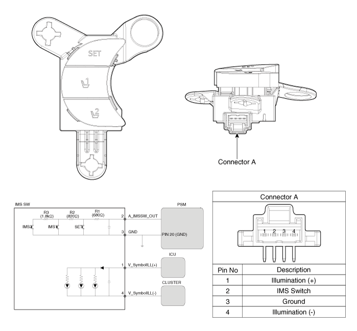
Repair procedures
| 1. | Disconnect the negative (-) battery terminal. |
| 2. | Remove the driver door trim. (Refer to Body - "Front Door Trim") |
| 3. | Remove the memory power switch (A) after disengaging the mounting clips. 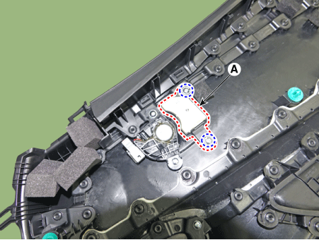
|
| 1. | Install the memory power seat control switch (IMS). |
| 3. | Connect the negative (-) battery terminal. |
| 1. | Remove the memory power seat connector 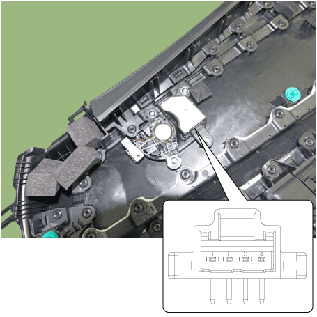
|
| 2. | When each switch is pressed, check the electricity flow between memory power seat switch connector and grounding, and if the electricity does not match the specification, replace the switch. 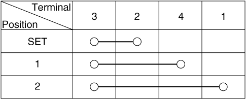
|
Description and operation
DescriptionBody Control Module Controls The Followings–
Wiper & Washer Control–
Defroster Control–
Dr ...
Power Seat Motor
Components and components location
Component Location1. Lumber support motor2. Reclining motor3. Front height motor4. Slide motor5. Rear height motor6. Reclining limit switch7. Lu ...
 Hyundai Elantra CN7: IMS(Integrated Memory System)


