 Hyundai Elantra CN7: Heater
Heater Unit
Components and components location
| Component Location |
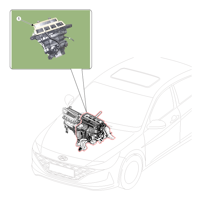
| 1. Heater unit assembly |
| Compoents |
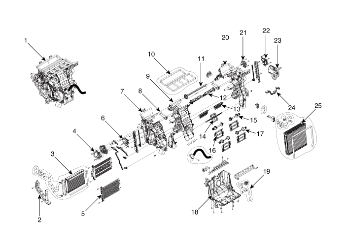
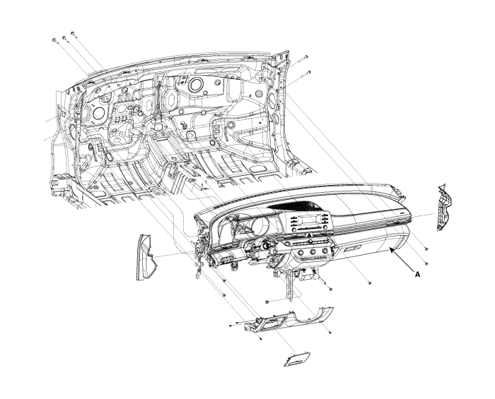
| 1. Heater unit assembly 2. Heater tube cover 3. Heater core assembly 4. Mode control actuator [LH] 5. Dummy PTC 6. Temperature control actuator [LH] 7. Heater case [LH] 8. Separator (Out) 9. Heater case [CTR] | 10. Heater & Blower duct seal 11. DEF door assembly 12. Vent door assembly 13. Floor door assembly 14. Mode door assembly 15. Shaft temperature door 16. Temperature door assembly 17. Shaft temperature door 18. Heater lower cover | 19. Drain hose 20. Heater case [RH] 21. Intake acutator 22. Temperature control actuator [RH] 23. Shower duct [RH] 24. Evaporator temperature sensor 25. Evaporator core assembly |
Repair procedures
| Replacement |
| 1. | Disconnect the negative (-) battery terminal. |
| 2. | Recover the refrigerant with a recovery / recycling / charging station. |
| 3. | When the engine is cool, drain the engine coolant from the radiator. (Refer to Engine Mechanical System - "Coolant") |
| 4. | Remove the bolts and the expansion valve (A) from the evaporator core.
|

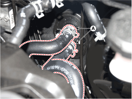
| 5. | Disconnect the heater hoses (A) from the heater unit.
|

| 6. | Remove the cowl top cover. (Refer to Body (Interior and Exterior) - "Cowl Top Cover") |
| 7. | Remove the battery. (Refer to Engine Electrical System - "Battery") |
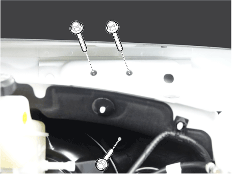
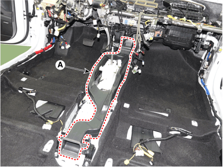
| 8. | Loosen the cowl cross member mounting bolts.
|
| 9. | Remove the front pillar trim. (Refer to Body (Interior and Exterior) - "Front Pillar Trim") |
| 10. | Remove the floor console assembly. (Refer to Body (Interior and Exterior) - "Floor Console Assembly") |
| 11. | Remove the shift lever assembly. (Refer to Automatic Transmission System - "Shift Lever") |
| 12. | Remove the cowl side trim. (Refer to Body (Interior and Exterior) - "Cowl Side Trim") |
| 13. | Remove the crash pad lower panel. (Refer to Body (Interior and Exterior) - "Crash Pad Lower Panel") |
| 14. | Remove the steering column shroud lower panel. (Refer to Body (Interior and Exterior) - "Steering Column Shroud Panel") |
| 15. | Remove the steering wheel. (Refer to Steering System - "Steering Wheel") |
| 16. | Remove the multifunction switch. (Refer to Body Electrical System - "Multifunction Switch") |
| 17. | Lower the steering column after loosening the mounting bolts. (Refer to Steering System - "Steering Column and Shaft") |
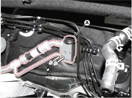
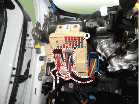
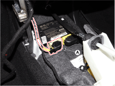
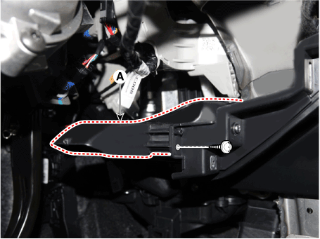
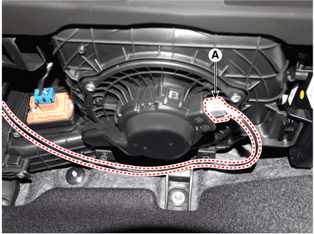
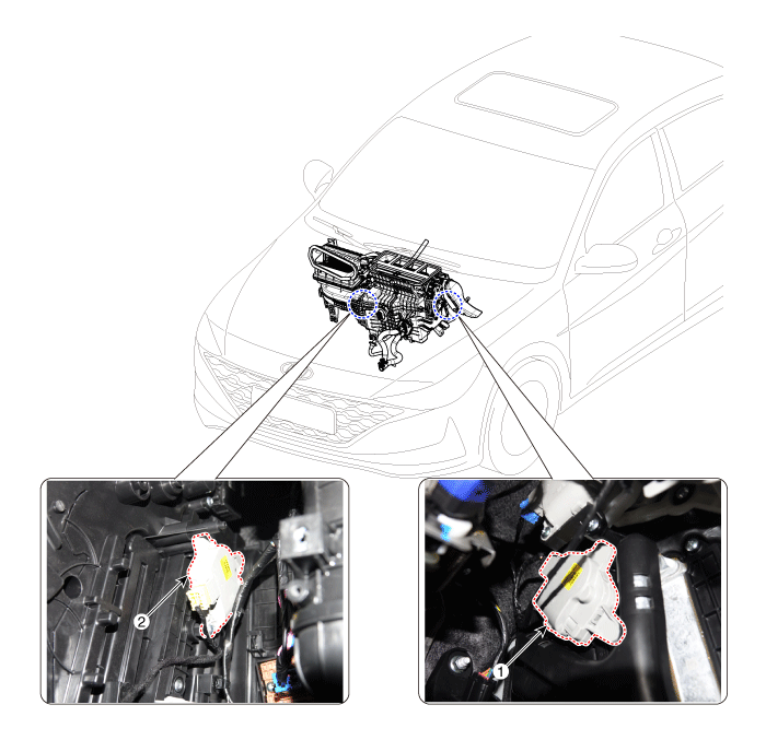
| 18. | Disconnect the junction box connectors (A).
|
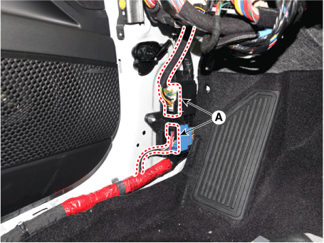
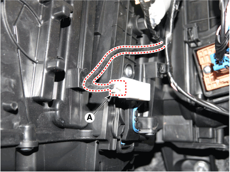
| 19. | Disconnect the multi box connectors (A). [LH]
[RH]
|
| 20. | Remove the center console duct (A).
|
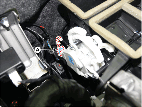
| 21. | Disconnect the airbag control module (SRSCM) connector (A).
|
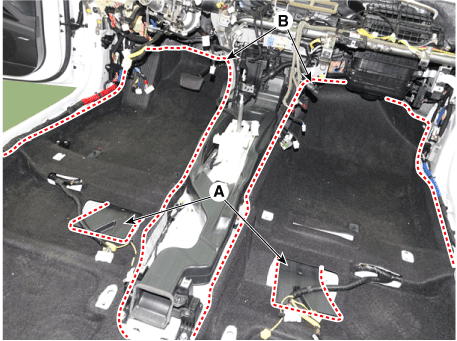
| 22. | Remove the rear air duct (A) and separate the floor carpet (B) to obtain space for removing the rear heating duct.
|
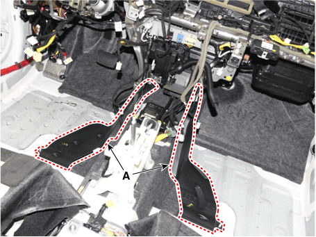
| 23. | Remove the front air duct (A).
|
| 24. | Loosen the cowl blower unit mounting bolts.
|
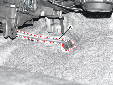
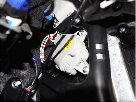
| 25. | Remove the drain hose (A).
|
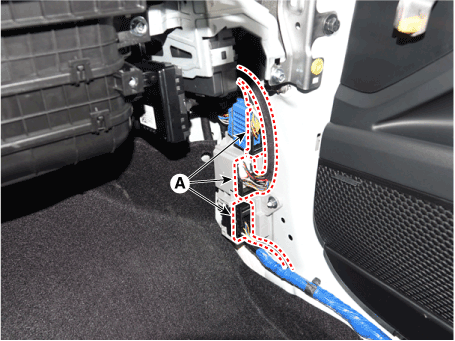
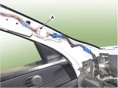
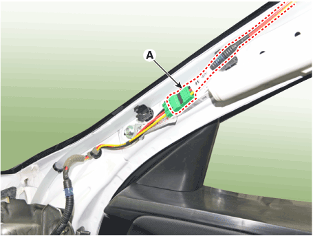
| 26. | Disconnect the connectors (A) and the mounting clips in the front pillar. [LH]
[RH]
|
| 27. | After loosening the bolts and nuts remove the main crash pad and cowl cross bar assembly (A) together.
|
| 28. | Disconnect the heater & blower unit connectors. [Driver's side]
[Passenger's side]
|
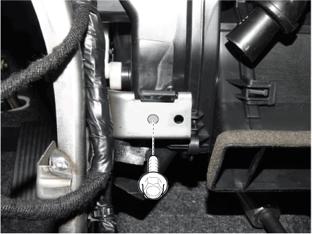
| 29. | Loosen the heater & blower unit mounting bolt.
|
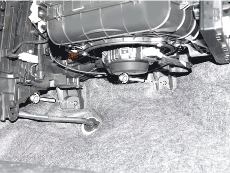
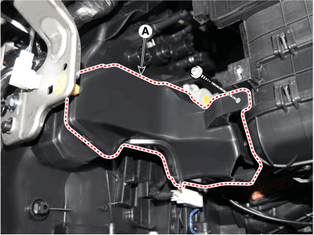
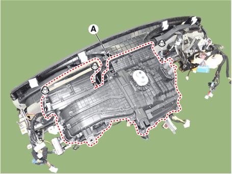
| 30. | Remove the heater and blower unit (A) from the crash pad after loosening the mounting nuts.
|
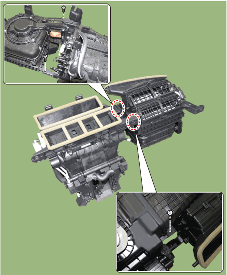
| 31. | Separate the heater unit (A) from the heater & blower unit assembly after loosening the screws.
|
| 32. | To install, reverse the removal procedure. |
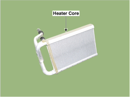
Heater Core
Repair procedures
| Replacement |
| 1. | Disconnect the negative (-) battery terminal. |
| 2. | Remove the heater and blower assembly. (Refer to Heater - "Heater Unit") |
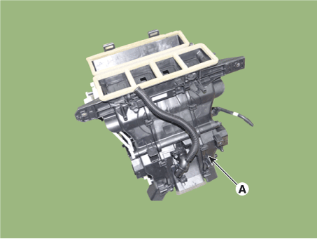
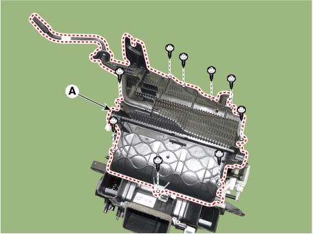
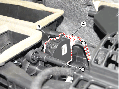
| 3. | Remove the heater core cover (A) after loosening the mounting screws.
|
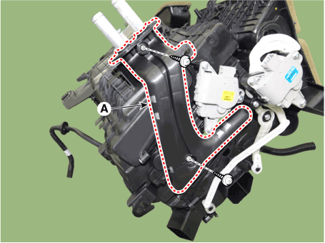
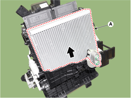
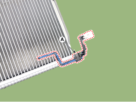
| 4. | Pull out the heater core (A) from the heater unit.
|
| 5. | To install, reverse the removal procedure.
|
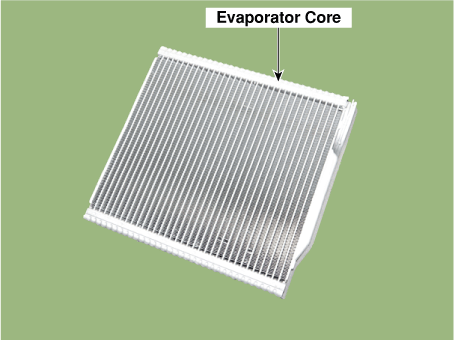
Evaporator Core
Repair procedures
| Replacement |
| 1. | Disconnect the negative (-) battery terminal. |
| 2. | Remove the heater and blower assembly. (Refer to Heater - "Heater Unit") |
| 3. | Remove the heater core cover (A) after loosening the mounting screws.
|
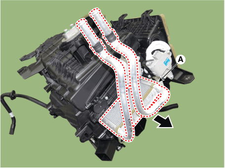
| 4. | Pull out the evaporator core (A) from the heater unit.
|
| 5. | Remove the evaporator temperature sensor (A).
|
| 6. | To install, reverse the removal procedure.
|
Temperature Control Actuator
Description and operation
| Description |
The temperature control actuator is located at the heater unit. It regulates the temperature by the procedure as follows.
The signal from the control unit adjusts the position of the temperature door by operating the temperature switch. Then the temperature will be regulated by the hot/cold air ratio decided by the position of the temperature door.
Components and components location
| Components Location |
| 1. Temperature control actuator [LH] | 2.Temperature control actuator [RH] |
Specifications
| Specifications |
|
Door Position
|
Voltage (V)
|
Error Detecting
|
| Max. cooling | 0.3 ± 0.15 | Low voltage : 0.1V or less High voltage : 4.9V or more |
| Max. heating | 4.7 ± 0.15 |
Repair procedures
| Inspection |
| 1. | Turn the ignition switch OFF. |
| 2. | Disconnect the temperature control actuator connector. |
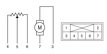
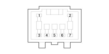
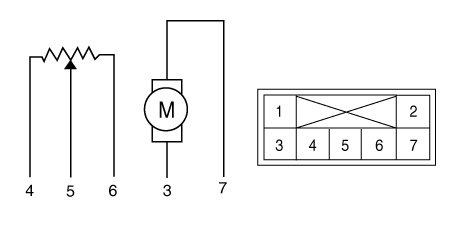
| 3. | Verify that the temperature control actuator operates to the cool position when connecting 12V to terminal 3 and grounding terminal 7. Verify that the temperature control actuator operates to the warm position when connected in reverse.
|
| 4. | Connect the temperature control actuator connector. |
| 5. | Turn the ignition switch ON. |
| 6. | Check the voltage between terminal 5 and 6. |
| 7. | If the measured voltage is not within specification, check the operation by replacing the existing temperature control actuator with a new genuine part. After that, determine whether replacement of the temperature control actuator is required or not. |
| Replacement |
[Driver's side]
| 1. | Disconnect the negative (-) battery terminal. |
| 2. | Remove the crash pad lower panel. (Refer to Body (Interior and Exterior) - "Crash Pad Lower Panel") |
| 3. | Loosen the mounting screw, remove the shower duct (A).
|
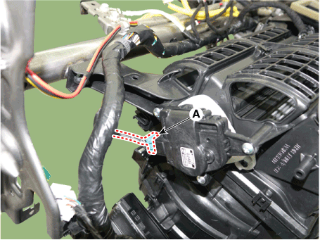
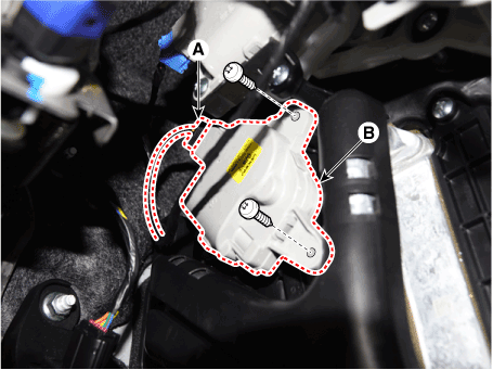
| 4. | Disconnect the connector (A) and then remove the driver's side temperature control actuator (B) after loosening the mounting screws.
|
| 5. | To install, reverse the removal procedure. |
[Passenger's side]
| 1. | Disconnect the negative (-) battery terminal. |
| 2. | Remove the glove box housing cover. (Refer to Body (Interior and Exterior) - "Glove Box Housing Cover") |
| 3. | Loosen the mounting screw, remove the shower duct (A).
|
| 4. | Disconnect the connector (A) and then remove the passenger's side temperature control actuator (B) after loosening the mounting screws.
|
| 5. | To install, reverse the removal procedure. |
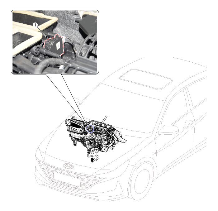
Mode Control Actuator
Description and operation
| Description |
The mode control actuator is located at the heater unit.
It adjusts the position of the mode door by operating the mode control actuator based on the signal of the A/C control unit. Pressing the mode select switch makes the mode control actuator shift in order of Vent → Bi-Level → Floor → Mix.
Components and components location
| Components Location |
| 1. Mode control actuator |
Specifications
| Specifications |
|
Door position
|
Voltage (V)
|
Error detecting
|
| Max. cooling | 0.3 ± 0.15 | Low voltage : 0.1V or less |
| Max. heating | 4.7 ± 0.15 | High voltage : 4.9V or more |
Repair procedures
| Inspection |
| 1. | Turn the ignition switch OFF. |
| 2. | Disconnect the mode control actuator connector. |
| 3. | Verify that the mode control actuator operates to the defrost mode when connecting 12V to terminal 3 and grounding terminal 7. Verify that the mode control actuator operates to the vent mode when connected in reverse.
|
| 4. | Connect the mode control actuator connector. |
| 5. | Turn the ignition switch ON. |
| 6. | Check the voltage between terminal 6 and 5. |
| 7. | If the measured voltage is not within specification, check the operation by replacing the existing mode control actuator with a new genuine part. After that, determine whether replacement of the temperature control actuator is required or not. |
| Replacement |
| 1. | Disconnect the negative (-) battery terminal. |
| 2. | Remove the main crash pad assembly. (Refer to Body (Interior and Exterior) - "Main Crash Pad Assembly") |
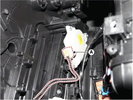
| 3. | Disconnect the connector (A) and then remove the mode control actuator (B) after loosening the mounting screws.
|
| 4. | To install, reverse the removal procedure. |
Auto Defoging Actuator
Description and operation
| Description |
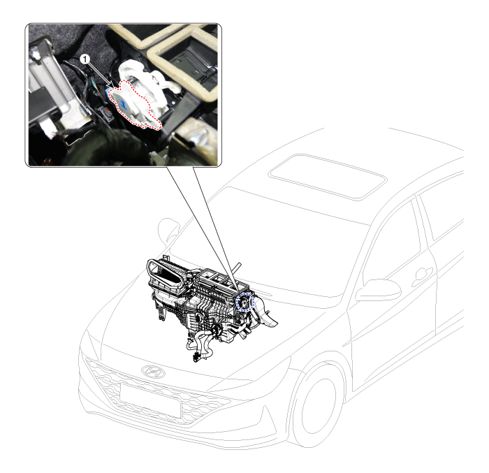
The auto defogging sensor is installed on front window glass. The sensor judges and sends signal if moisture occurs to blow out wind for defogging. The air conditioner control module receives a signal from the sensor and restrains moisture and eliminates defog by the intake actuator, A/C, auto defogging actuator, blower motor rpm and mode actuator.
Components and components location
| Components Location |
| 1. Auto defoging actuator |
Specifications
| Specifications |
|
Door position
|
Voltage (V)
|
Error detecting
|
| Max. cooling | 0.3 ± 0.15 | Low voltage : 0.1V or less |
| Max. heating | 4.7 ± 0.15 | High voltage : 4.9V or more |
Repair procedures
| Inspection |
| 1. | Turn the ignition switch OFF. |
| 2. | Disconnect the auto defogging connector. |
| 3. | Verify that the auto defogging actuator operates to the open position when connecting 12V to terminal 3 and grounding terminal 7. Verify that the auto defogging actuator operates to the close position when connected in reverse.
|
| 4. | Connect the auto defogging actuator connector. |
| 5. | Turn the ignition switch ON. |
| 6. | Check the voltage between terminals 6 and 5. |
| 7. | If the measured voltage is not within specification, check the operation by replacing the existing auto defogging actuator with a new genuine part. After that, determine whether replacement of the auto defogging actuator is required or not. |
| Replacement |
| 1. | Disconnect the negative (-) battery terminal. |
| 2. | Remove the main crash pad assembly. (Refer to Body (Interior and Exterior) - "Main Crash Pad Assembly") |
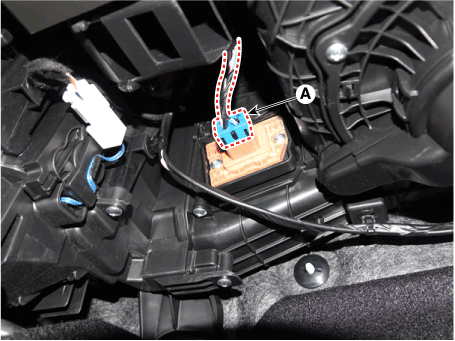
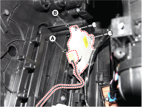
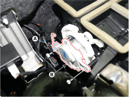
| 3. | Disconnect the connector (A) and then remove the auto defoging actuator (B) after loosening the mounting screws.
|
| 4. | To install, reverse the removal procedure. |

