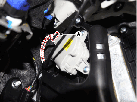
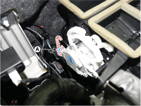
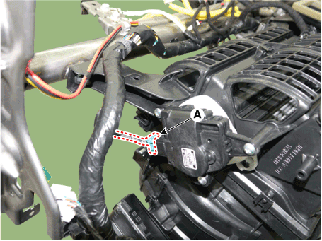
 Hyundai Elantra CN7: Blower
Blower Unit
Components and components location
| Component Location |
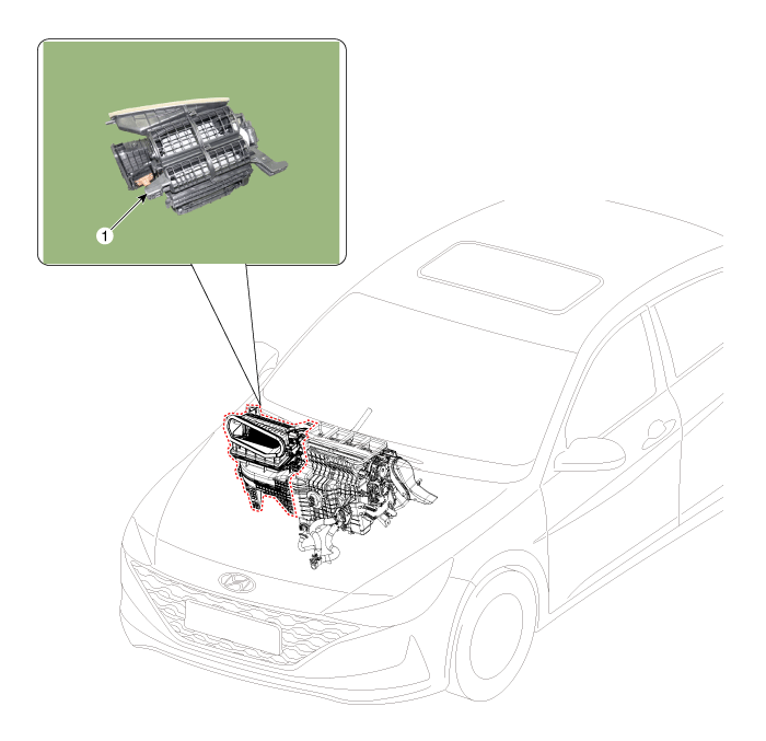
| 1. Blower unit assembly |
| Components |
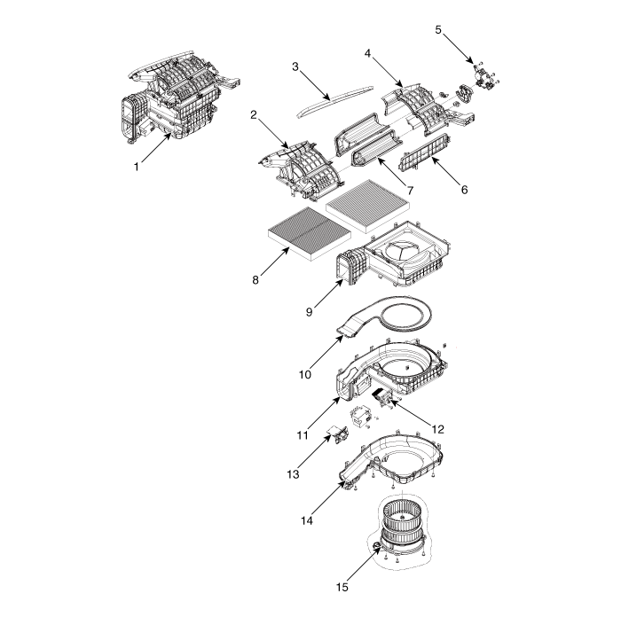
| 1. Blower unit assebmly 2. Blower upper cover [LH] 3. Duct seal 4. Blower upper cover [RH] 5. Intake actuator 6. Air filter cover 7. Intake door | 8. Air filter 9. Blower upper case 10. Blower plate 11. Blower lower case 12. Power mosfet 13. Resistor 14. Blower lower cover 15. Blower motor |
Repair procedures
| Replacement |
| 1. | Disconnect the negative (-) battery terminal. |
| 2. | Recover the refrigerant with a recovery / recycling / charging station. |
| 3. | When the engine is cool, drain the engine coolant from the radiator. (Refer to Engine Mechanical System - "Coolant") |
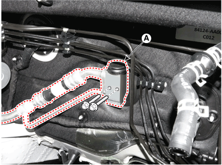
| 4. | Remove the bolts and the expansion valve (A) from the evaporator core.
|
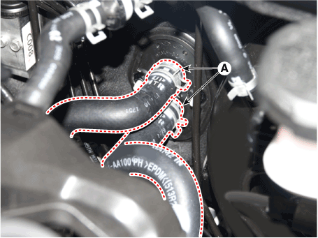
| 5. | Disconnect the heater hoses (A) from the heater unit.
|
| 6. | Remove the cowl top cover. (Refer to Body (Interior and Exterior) - "Cowl Top Cover") |
| 7. | Remove the battery. (Refer to Engine Electrical System - "Battery") |
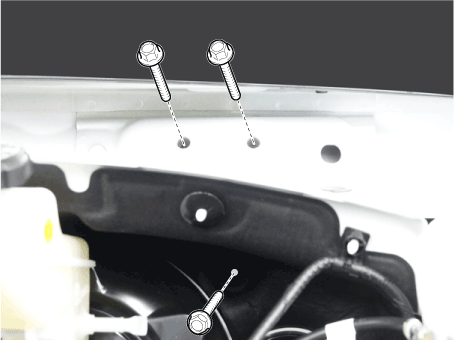
| 8. | Loosen the cowl cross member mounting bolts.
|
| 9. | Remove the front pillar trim. (Refer to Body (Interior and Exterior) - "Front Pillar Trim") |
| 10. | Remove the floor console assembly. (Refer to Body (Interior and Exterior) - "Floor Console Assembly") |
| 11. | Remove the shift lever assembly. (Refer to Automatic Transmission System - "Shift Lever") |
| 12. | Remove the cowl side trim. (Refer to Body (Interior and Exterior) - "Cowl Side Trim") |
| 13. | Remove the crash pad lower panel. (Refer to Body (Interior and Exterior) - "Crash Pad Lower Panel") |
| 14. | Remove the steering column shroud lower panel. (Refer to Body (Interior and Exterior) - "Steering Column Shroud Panel") |
| 15. | Remove the steering wheel. (Refer to Steering System - "Steering Wheel") |
| 16. | Remove the multifunction switch. (Refer to Body Electrical System - "Multifunction Switch") |
| 17. | Lower the steering column after loosening the mounting bolts. (Refer to Steering System - "Steering Column and Shaft") |
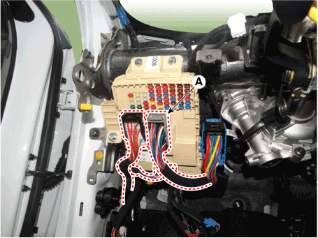
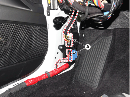
| 18. | Disconnect the junction box connectors (A).
|
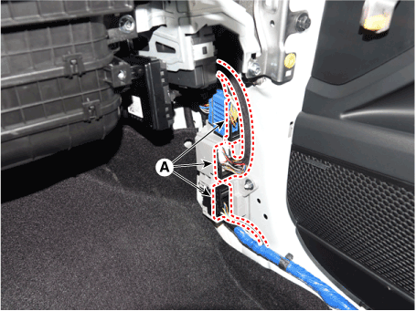
| 19. | Disconnect the multi box connectors (A). [LH]
[RH]
|
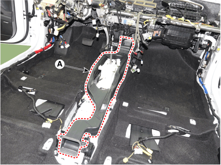
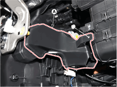
| 20. | Remove the center console duct (A).
|
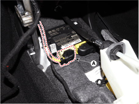
| 21. | Disconnect the airbag control module (SRSCM) connector (A).
|
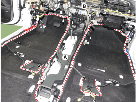
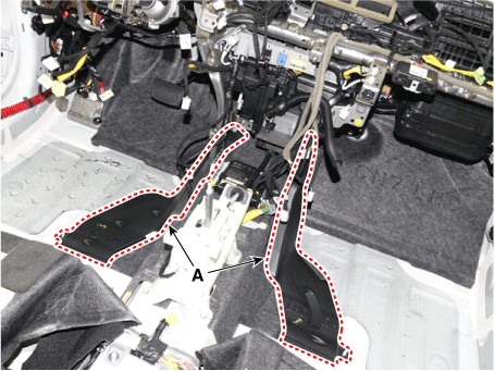
| 22. | Remove the rear air duct (A) and separate the floor carpet (B) to obtain space for removing the rear heating duct.
|
| 23. | Remove the front air duct (A).
|
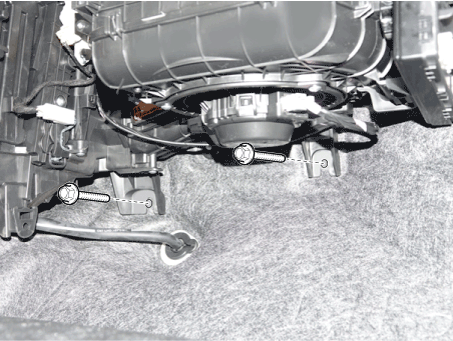
| 24. | Loosen the cowl blower unit mounting bolts.
|
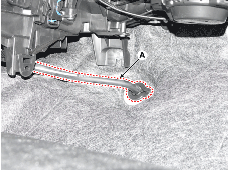
| 25. | Remove the drain hose (A).
|
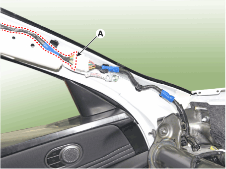
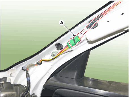
| 26. | Disconnect the connectors (A) and the mounting clips in the front pillar. [LH]
[RH]
|
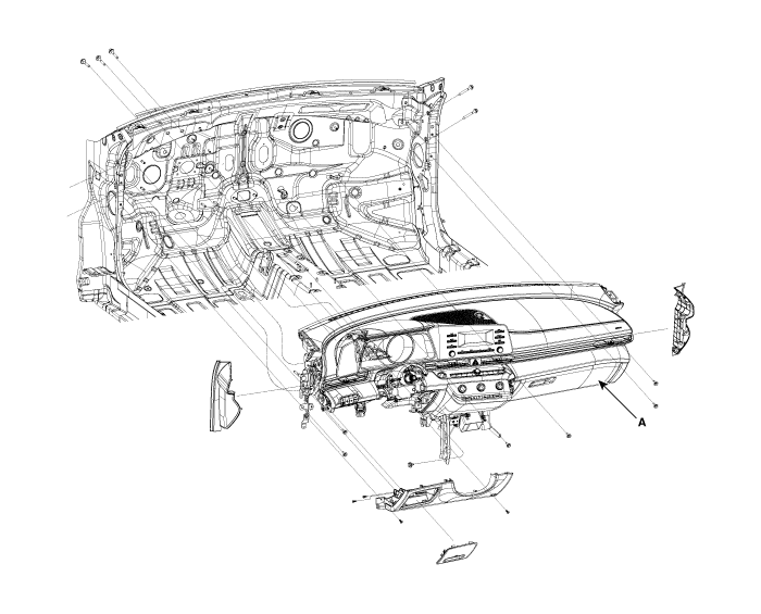
| 27. | After loosening the bolts and nuts remove the main crash pad and cowl cross bar assembly (A) together.
|
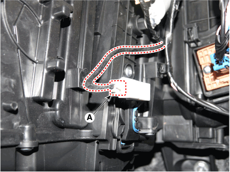
| 28. | Disconnect the heater & blower unit connectors. [Driver
[Passenger's side]
|
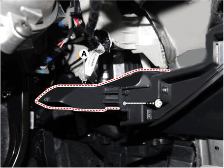
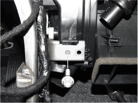
| 29. | Loosen the heater & blower unit mounting bolt.
|
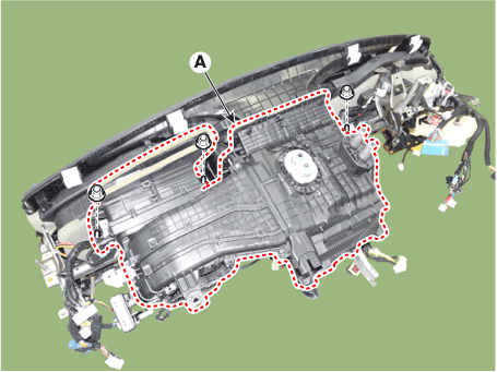
| 30. | Remove the heater and blower unit (A) from the crash pad after loosening the mounting nuts.
|
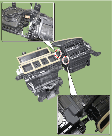
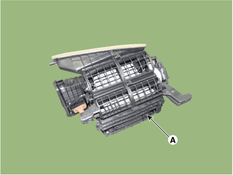
| 31. | Separate the blower unit (A) from the heater & blower unit assembly after loosening the screws.
|
| 32. | To install, reverse the removal procedure. |
Blower Motor
Repair procedures
| Inspection |
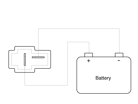
| 1. | Connect the battery voltage and check the blower motor rotation.
|
| Replacement |
| 1. | Disconnect the negative (-) battery terminal. |
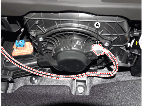
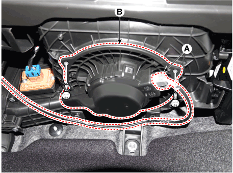
| 2. | Disconnect the blower motor connector (A) and then remove the blower motor (B) after loosening the screws.
|
| 3. | To install, reverse the removal procedure |
Power Mosfet
Description and operation
| Description |
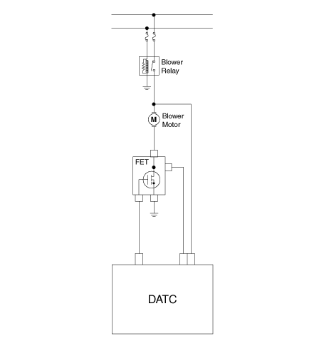
It is installed to the DATC and adjusts the fan rpm by precisely controlling the voltage applied to the blower motor.
Repair procedures
| Inspection |
| 1. | Manually operate the control switch and measure the voltage of the blower motor. |
| 2. | Select the control switch to raise the voltage until high speed.
|
| Replacement |
| 1. | Disconnect the negative (-) battery terminal. |
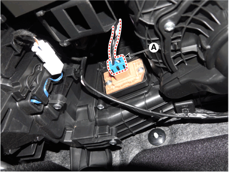
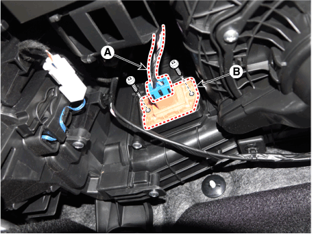
| 2. | Disconnect the power mosfet connector (A) and then remove the power mosfet (B) after loosening the mounting screws.
|
| 3. | To install, reverse the removal procedure. |
Blower Resistor (Manual)
Repair procedures
| Inspection |
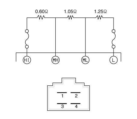
| 1. | Measure the resistance between the terminals. |
| 2. | The measured resistance is not within specification, the blower resistor must be replaced. (After removing the resistor)
|
| Replacement |
| 1. | Disconnect the negative (-) battery terminal. |
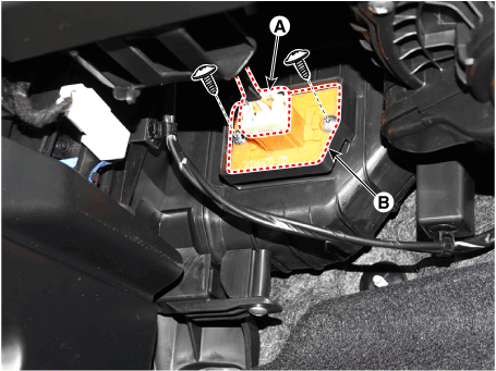
| 2. | Disconnect the connector (A) and then remove the blower resistor (B) after loosening the mounting screws.
|
| 3. | To install, reverse the removal procedure. |
Climate Control Air Filter
Description and operation
| Description |
The climate control air filter is located in the blower unit. It eliminates foreign materials and odor. The particle filter performs a role as an odor filter as well as a conventional dust filter to ensure comfortable interior environment.
Repair procedures
| Replacement |
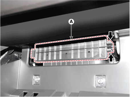
| 1. | Remove the glove box. (Refer to Body (Interior and Exterior) - "Glove Box") |
| 2. | Remove the filter cover (A) by pressing the knob.
|
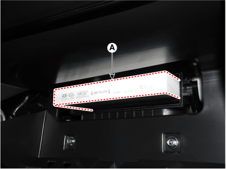
| 3. | Replace the air filter (A) with a new one according to the direction of air filter.
|
| 4. | To install, reverse the removal procedure. |
Intake Actuator
Description and operation
| Description |
The intake actuator is located at the blower unit. It regulates the intake door by a signal from the control unit. Pressing the intake selection switch will shift between recirculation and fresh air modes.
Components and components location
| Components Location |
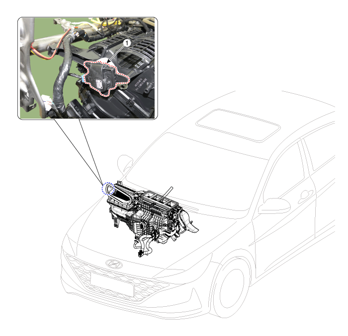
| 1. Intake actuator |
Specifications
| Specifications |
|
Door position
|
Voltage (V)
|
Error detecting
|
| Max. cooling | 0.3 ± 0.15 | Low voltage : 0.1V or less |
| Max. heating | 4.7 ± 0.15 | High voltage : 4.9V or more |
Repair procedures
| Inspection |
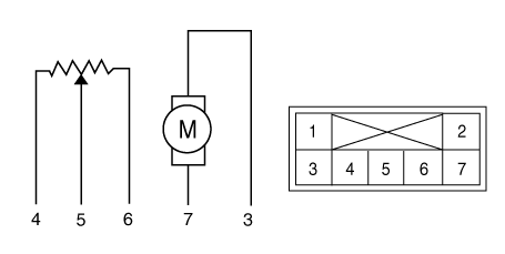
| 1. | Verify that the intake actuator operates to the fresh position when connecting 12V to terminal 3 and grounding terminal 7. |
| 2. | Verify that the intake actuator operates to the recirculation position when connected in reverse.
|
| 3. | Connect the intake actuator connector. |
| 4. | Turn the ignition switch ON. |
| 5. | Check the voltage between terminal 6 and 5. |
| 6. | If the measured voltage is not within specification, check the operation by replacing the existing intake actuator with a new genuine part. After that, determine whether replacement of the temperature control actuator is required or not. |
| Replacement |
| 1. | Disconnect the negative (-) battery terminal. |
| 2. | Remove the Heater & Blower unit assebmly. (Refer to Heater - "Heater Unit") |
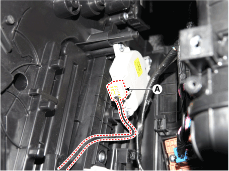
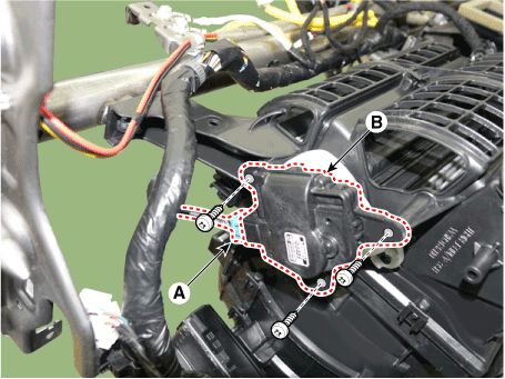
| 3. | Disconnect the connector (A) and then remove the intake actuator (B) after loosening the mounting screws.
|
| 4. | To install, reverse the removal procedure. |

