 Hyundai Elantra CN7: Emergency Call System
Description and operation
| Description |
Emergency Call (eCall)
When an accident occurs or the user's request is detected, it notifies the call center of the vehicle status using the wireless network so that the center can provide necessary emergency service.
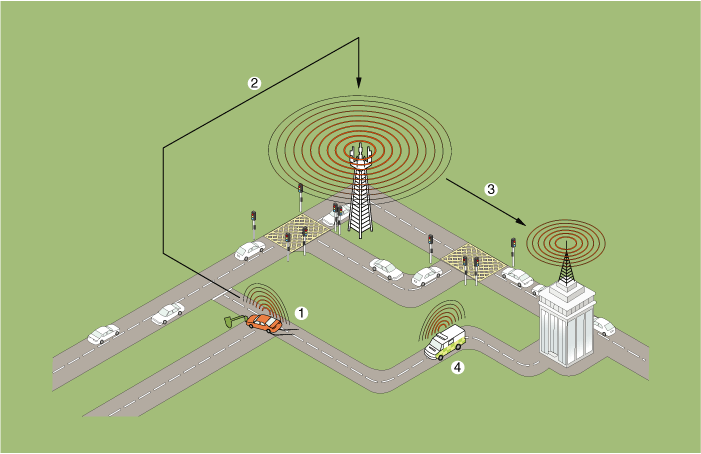
| 1. Emergency Call 2. Radio Communication network | 3. Public-Safety Answering Point (PSAP) 4. Emergency rescue service |
eCall Function
| 1. | Automatic notification function : It detects airbag signal that is triggered by accident and automatically notifies the call center of the accident.
|
| 2. | Manual notification function : The driver decides to operate the SOS button to notify the call center of the accident manually.
|
Configuration of eCall Controller
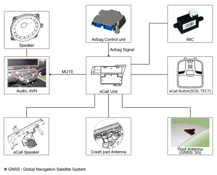
Input button & Indicator
SOS button : Press the button to place a call to the call center.
SOS TECT button : Press the button for 10 seconds or more to perform the test mode and reset the eCall system.
LED indicator lamp : The red and green LEDs turn on for 3 seconds after the ACC is on and stay turned off in standby until the key is turned off.
The red LED turns on when there is a problem with the eCall system.
The green LED turns on when the eCall system is operating normally.
Components and components location
| Components |
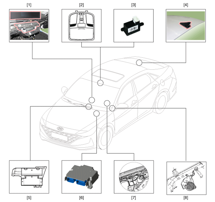
| 1. AVN head unit & monitor 2. Emergency call system button 3. Emergency call system MIC 4. Roof antenna | 5. Emergency call unit 6. Supplemental Restraint System Control Module (SRSCM) 7. Emergency call crash pad antenna 8. Emergency call speaker |
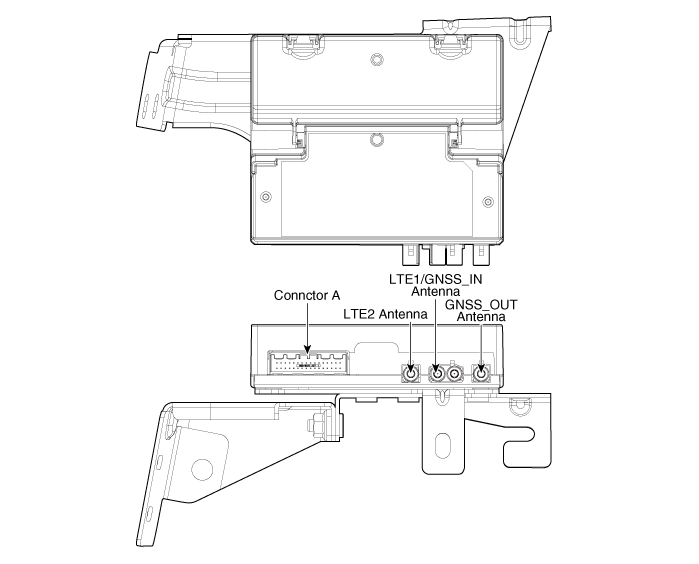
Emergency Call (eCall) Unit
Components and components location
| Component |
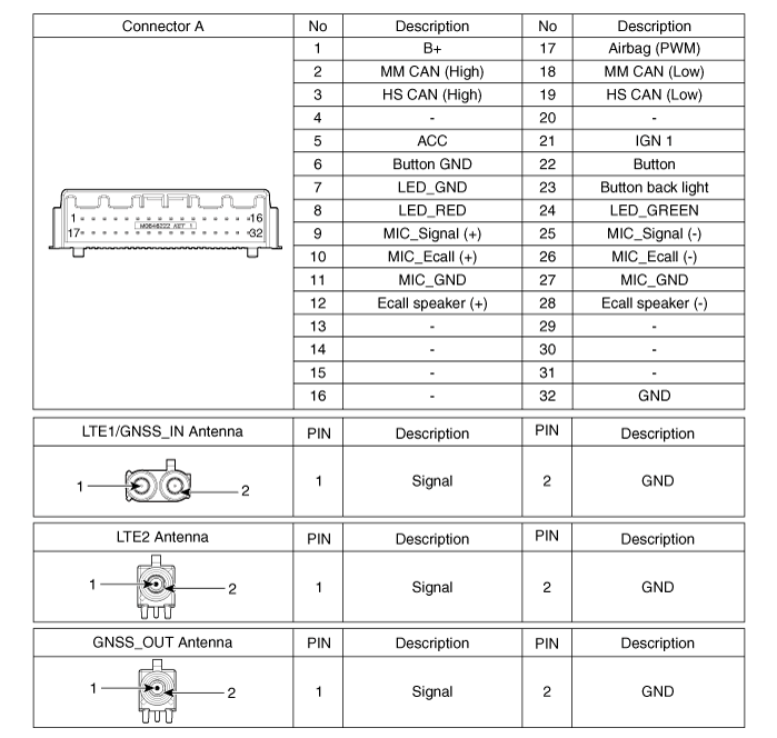
|
Repair procedures
| Removal |
You must make sure turn RED LED ON if you do any of the following.
|
|
eCall Unit
| 1. | Disconnect the negative (-) battery terminal. |
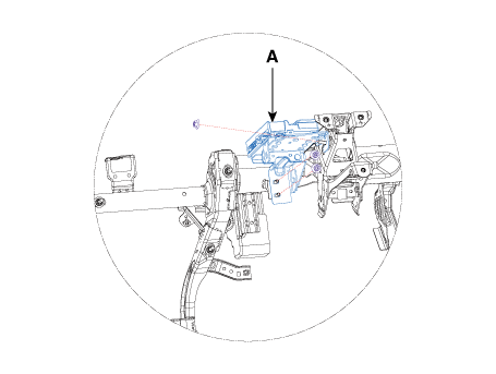
| 2. | Remove the crash pad lower panel. (Refer to body - "Crash Pad Lower Panel") |
| 3. | Remove the eCall unit (A) after loosening the mounting screws and disconnecting the eCall unit connectors.
|
eCall Speaker
| 1. | Disconnect the negative (-) battery terminal. |
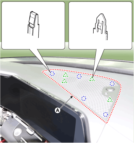
| 2. | Using a screwdriver or remover, remove the crash pad center speaker grille (A).
|
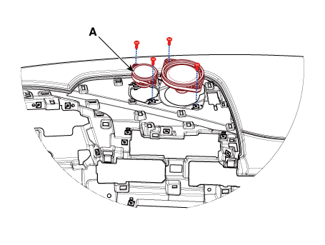
| 3. | Remove the ecall speaker (A) after loosening mounting screws.
|
| 4. | Disconnect the speaker connector. |
| Replacement |
eCall Unit Back Up Battery (BUB)
| 1. | Disconnect the negative (-) battery terminal. |
| 2. | Remove the eCall Unit. |
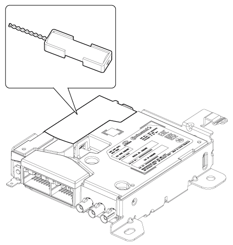
| 3. | If it is necessary to replace the back-up battery, remove the back-up battery after removing the back-up battery cover (A).
|
| Installation |
You must carry out Test Mode if you do any of the following.
|
eCall Unit
| 1. | Install the eCall unit. |
| 2. | Install the crash pad lower panel. |
| 3. | Connect the negative (-) battery terminal. |
eCall Speaker
| 1. | Install the eCall speaker. |
| 2. | Connect the negative (-) battery terminal. |
| Inspection |
Inspecting Back-Up Battery
Back-up battery (BUB) embedded in the eCall system has a finite lifespan and using it for a long time may decrease its charging/discharging performance.
The back-up battery guarantees the operation of the eCall system when the vehicle battery cannot be used due to an accident. Be sure to inspect the back-up battery if the red LED turns on and replace it if necessary.
|
|
|
Inspection with Diagnostic Tools
In the eCall system, failure can be quickly diagnosed by using the vehicle diagnostic system.
The diagnostic system provides the following information.
| 1) | Self diagnosis : Checking failure and code number (DTC) |
| 2) | Current data : Checking the system input/output data state |
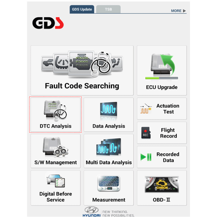
| 1. | Select the "Car Model" and the "eCall System" to be checked in order to check the vehicle with the tester. |
| 2. | To inquire the cause of trouble for each module by self diagnosis, select 'Diagnostic Trouble Code'.
|
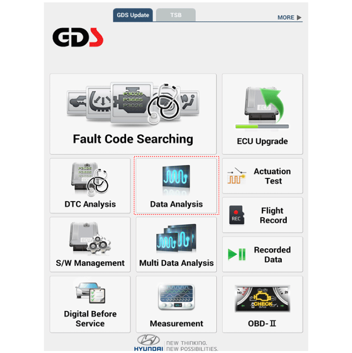
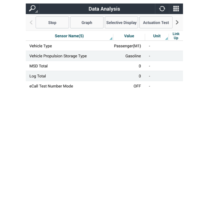
| 3. | Select the 'Current Data' menu to check the current state of the input/output data.
|
eCall System Reset
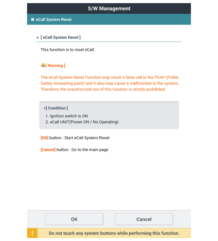
The eCall System Reset function is to reset when eCall is locked or stopped.
|
| 1. | Turn the ignition switch OFF. |
| 2. | Connect the diagnostic tools. |
| 3. | Turn the ignition switch ON without the engine running. |
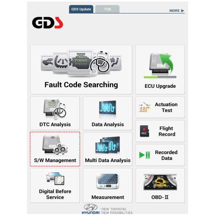
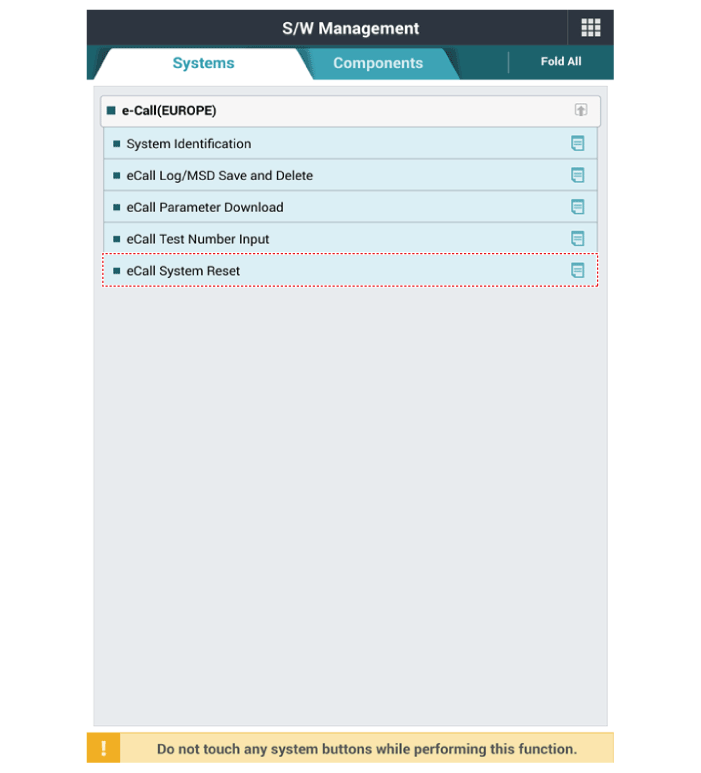
| 4. | Select the "Car Model" and "S/W Management".
|
| 5. | Select the "eCall System Reset"
|
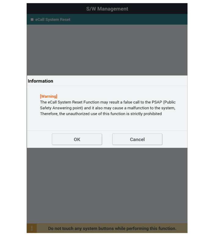
| 6. | Follow the screen instructions to perform the "eCall System Reset".
|
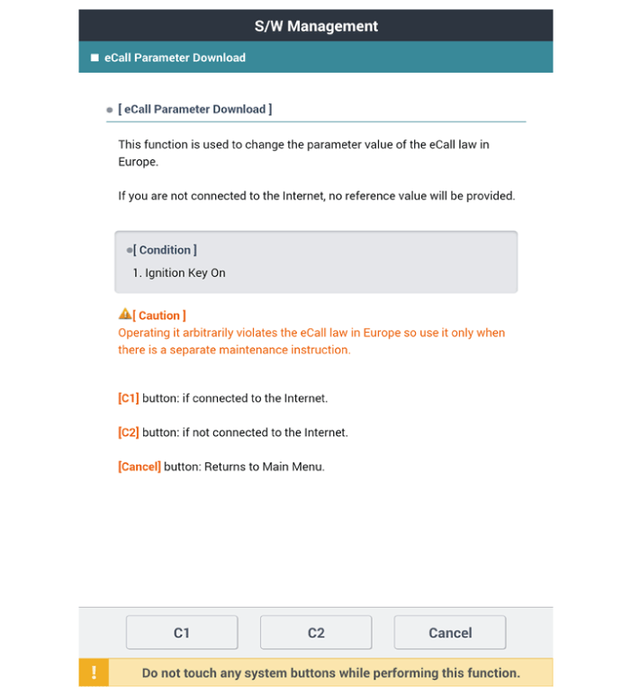
eCall Parameter Download
eCall Parameter Download is used to change the parameter value of the eCall law in Europe.
| 1. | Turn the ignition switch OFF. |
| 2. | Connect the diagnostic tools. |
| 3. | Turn the ignition switch ON without the engine running. |
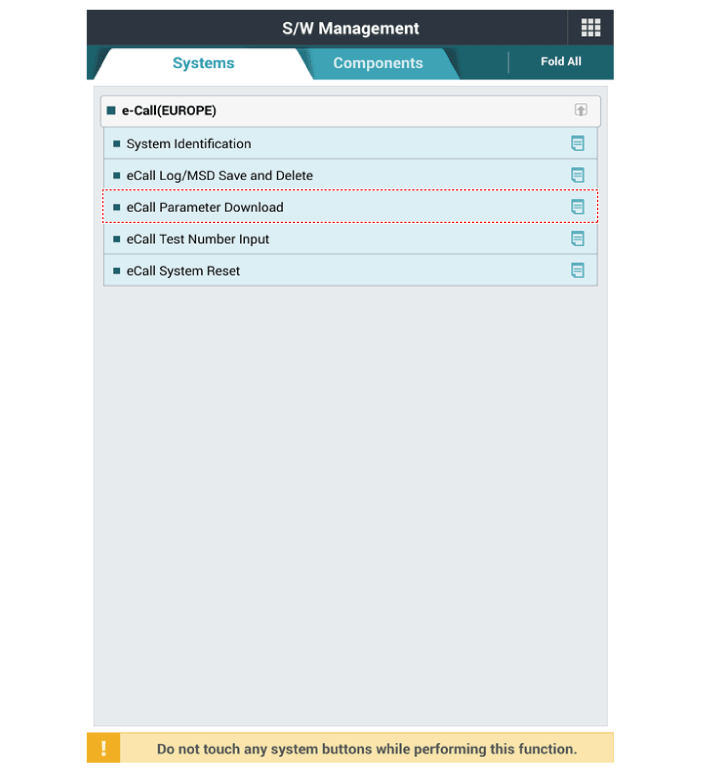
| 4. | Select the "Car Model" and "S/W Management".
|
| 5. | Select the "eCall Parameter Download"
|
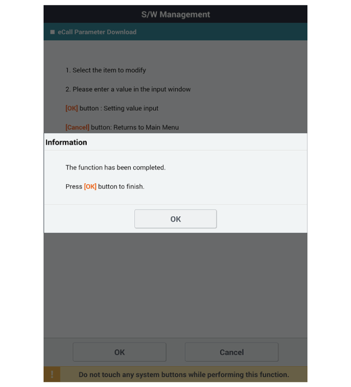
| 6. | Follow the screen instructions to perform the "eCall Parameter Download".
|
Emergency Call (eCall) Button
Components and components location
| Component |
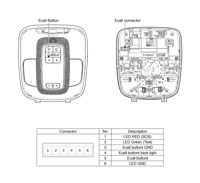
Repair procedures
| Removal |
| 1. | Disconnect the negative (-) battery terminal. |
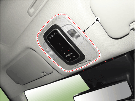
| 2. | Using a remover and remove the overhead console (A).
|
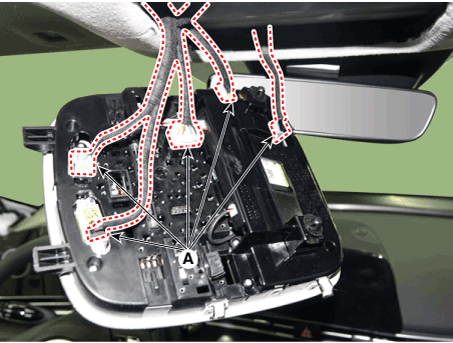
| 3. | Disconnect the overhead console connectors (A).
|
| Installation |
| 1. | Install the eCall button and button cover. |
| 2. | Install the overhead console assembly after connecting the connector. |
| 3. | Connect the negative (-) battery terminal. |
Emergency Call (eCall) Antenna
Schematic diagrams
| Components |
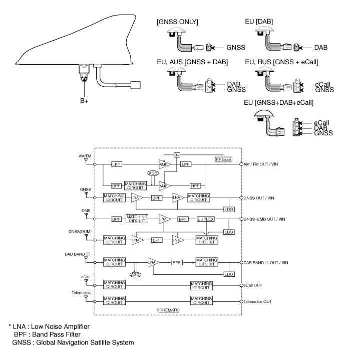
Repair procedures
| Removal |
Roof Antenna
| 1. | Disconnect the negative (-) battery terminal. |
| 2. | Remove the roof trim. (Refer to Body - "Roof Trim Assembly") |
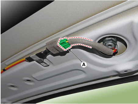
| 3. | Disconnect the roof antenna connector (A).
|
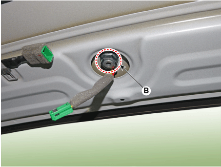
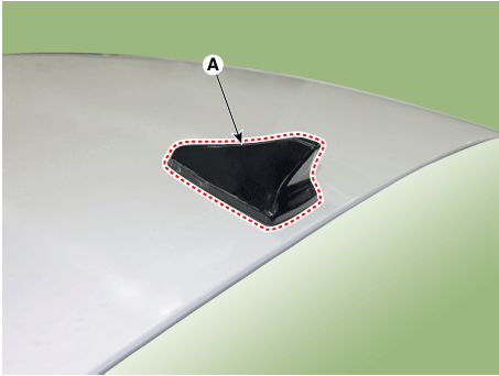
| 4. | Remove the roof antenna (A) after loosening a nut (B).
|
Crash Pad Antenna
| 1. | Disconnect the negative (-) battery terminal. |
| 2. | Remove the main crash pad assembly. (Refer to Body - "Main Crash Pad Assembly") |
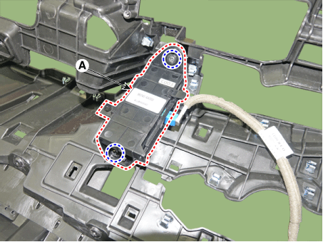
| 3. | Loosen the mounting screws and then remove the crash pad antenna (A).
|
| Installation |
Roof Anenna
| 1. | Connect the roof antenna connectors. |
| 2. | Install the roof trim assembly.
|
Crash Pad Antenna
| 1. | Connect the roof antenna connectors and install the roof antenna. |
| 2. | Install the main crash pad assembly. |


