 Hyundai Elantra CN7: AVN System
Description and operation
| Description |
AVN System
The AVN system has improved information search and easiness of manipulation for the driver by simplifying the system operation experience and unifying the display of the user information such as multimedia and car information.
The system is basically composed of a keyboard for the operation of combined function, LCD monitor, a head unit with Bluetooth handsfree calling, voice recognition and navigation, music amplifier and the media unit that connects with other outside devices.
| 1. | Simplification of user interface : the multimedia and car information are displayed on the monitor. |
| 2. | Networked electronic parts : Efficient information transmission through CAN communications. |
| 3. | Up-to-date technologies integrated :
|
System Block Diagram
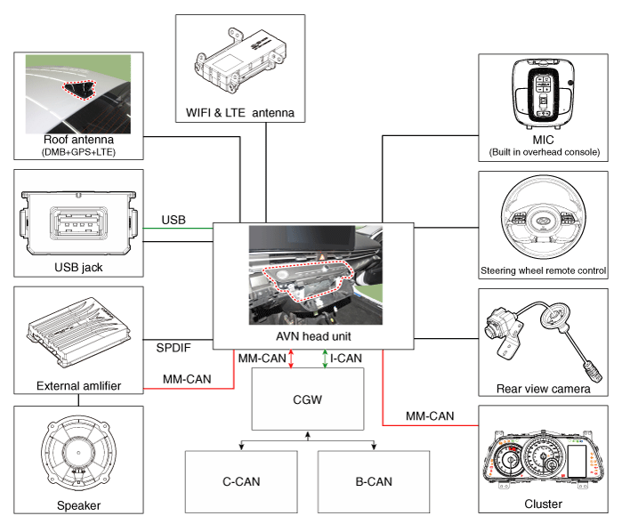
| • | B-CAN : Body Controller Area Network |
| • | MM-CAN : Multi-Media Controller Area Network |
Limitations of the Navigation System
GPS Signal Reception State
As the GPS satellite frequency is received/transmitted in straight lines, reception may not work if hiding devices are placed on or near the GPS antenna or when traveling through the following locations.
| • | Tunnels |
| • | Basement parking structures |
| • | Underneath an overpass |
| • | Roads within forested areas |
| • | Areas near high rise buildings |
| • | Roads within canyons |
Vehicle Position Display
| 1. | If multipass errors occur due to reflections from buildings or related causes, the current position mark on the navigation may differ from the actual position of the vehicle. |
| 2. | The position of the vehicle on the navigation may be different from the actual position if the vehicle is under the occur, driving for a short period of time will vehicle through map matching or GPS information (several minutes may be necessary in certain cases).
|
Route Guidance
Suitable route guidance may not occur caused by search conditions or the driving position.
| • | Guidance to go straight may be given while driving on a straight road. |
| • | Guidance may not be given even when having turned at an intersection. |
| • | There are certain intersections in which guidance may not occur. |
| • | A route guidance signaling entrance into a no enter zone may occur (No enter zone, road under construction, etc.) |
| • | Guidance may be given to a position removed from the actual destination if roads to reach the actual destination do not exist or are too narrow. |
| • | Faulty voice guidance may be given if the vehicle breaks from the designated route (ex : if a turn is made at an intersection while the navigation provided guidance to go straight). |
| • | Map Data may be missing or incorrect causing route guidance to not be given. |
Route Re-calculation
The following phenomena may occur after conducting route recalculation.
| • | Guidance may be given to a position differing from the current position when turning at an intersection. |
| • | Route recalculation may take a longer period of time when driving under high speeds. |
| • | A route guidance signaling for a U-Turn in a No U-Turn location may occur. |
| • | A route guidance signaling entrance into a no enter zone may occur (No enter zone, road under construction, etc). |
| • | Guidance may be given to a position removed from the actual destination do not exist or are too narrow. |
| • | Faulty voice guidance may be given if the vehicle breaks from the designated route (ex : if a turn is made at an intersection while the navigation provided guidance to go straight) |
Components and components location
| Component Location |
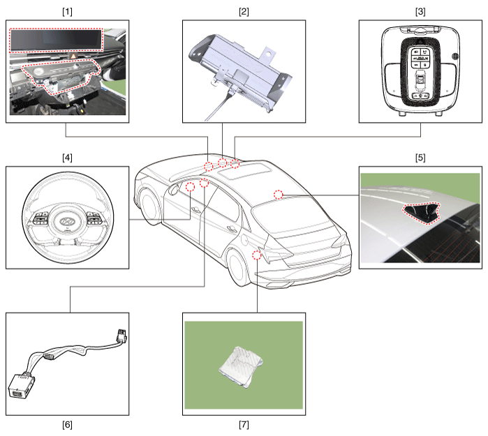
| 1. AVN head unit 2. Crash pad antenna 3. Bluelink keyboard & Hands-free mic (Built-in overhead console) 4. Steering wheel remote control | 5. Roof antenna 6. USB jack 7. External amplifier (Option) |
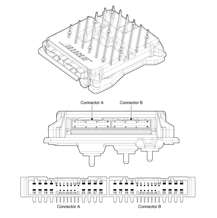
AVN(Audio Video Navigation) head unit
Components and components location
| Components |
Middle East
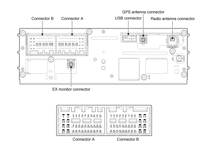
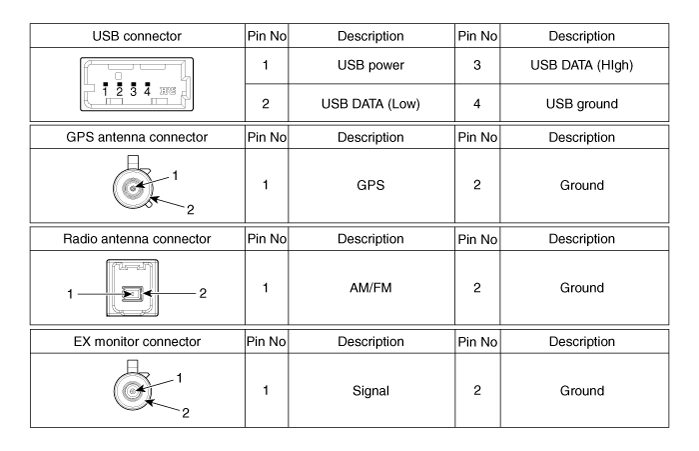
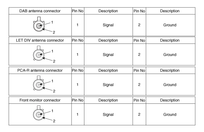
Connector Pin Information
|
No
|
Connector A (Int AMP)
|
Connector A (Ext AMP)
|
Connector B
|
| 1 | Rear left speaker (+) | - | - |
| 2 | Reart left speaker (-) | - | MIC Signal (+) |
| 3 | - | AMP Navi Voice (+) | - |
| 4 | - | AMP SPDIF (HI) | - |
| 5 | - | - | Antenna Powr |
| 6 | Camera Power | Camera Power | ILL (+) |
| 7 | Camera Video | Camera Video | MM CAN (HI) |
| 8 | - | - | - |
| 9 | - | - | - |
| 10 | - | - | B+ |
| 11 | - | - | B+ |
| 12 | Steering wheel remote | Steering wheel remote | GND |
| 13 | Front lift speaker (+) | - | GND |
| 14 | Front lift speaker (-) | - | MIC GND |
| 15 | Front right speaker (-) | - | MIC Signal (-) |
| 16 | Front right speaker (+) | - | - |
| 17 | - | AMP Navi Voice (-) | - |
| 18 | - | AMP SPDIF (LOW) | - |
| 19 | - | AMP SPDIF GND | - |
| 20 | Camera Power GND | Camera Power GND | MM CAN (LOW) |
| 21 | Camera Video GND | Camera Video GND | - |
| 22 | - | - | ACC |
| 23 | - | - | - |
| 24 | - | - | - |
| 25 | - | - | - |
| 26 | Steering wheel remote GND | Steering wheel remote GND | - |
| 27 | Rear right speaker (-) | - | - |
| 28 | Rear right speaker (+) | - | - |
| 29 | - | - | - |
| 30 | - | - | - |
| 31 | - | - | - |
| 32 | - | - | - |
| 33 | Camera shield ground | - | IGN 1 |
| 34 | - | - | - |
| 35 | - | - | - |
| 36 | - | - | |
| 37 | - | - | |
| 38 | Speed | Speed |
General
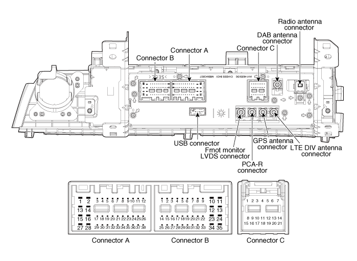
Connector Pin Information
|
No
|
Connector A (Ext AMP)
|
Connector B
|
Connector C
|
| 1 | - | - | - |
| 2 | - | MIC Signal (+) | I-CAN (HI) |
| 3 | AMP Navi Voice (+) | - | - |
| 4 | AMP SPDIF (HI) | - | - |
| 5 | - | - | - |
| 6 | Camera Power | ILL (+) | - |
| 7 | Camera Video | MM CAN (HI) | - |
| 8 | - | - | - |
| 9 | - | - | I-CAN (LOW) |
| 10 | - | B+ | - |
| 11 | USB Detect | B+ | - |
| 12 | Steering wheel remote | GND | - |
| 13 | - | GND | - |
| 14 | - | - | - |
| 15 | - | MIC Signal (-) | - |
| 16 | - | - | MTS Key |
| 17 | AMP Navi Voice (-) | - | - |
| 18 | AMP SPDIF (LOW) | - | - |
| 19 | AMP SPDIF GND | ILL (-) | - |
| 20 | Camera Power GND | MM CAN (LOW) | - |
| 21 | Camera Video GND | - | - |
| 22 | - | ACC | |
| 23 | - | - | |
| 24 | - | Front monitor power | |
| 25 | - | - | |
| 26 | Steering wheel remote GND | - | |
| 27 | - | - | |
| 28 | - | - | |
| 29 | - | - | |
| 30 | - | - | |
| 31 | - | - | |
| 32 | - | - | |
| 33 | Camera shield ground | IGN 1 | |
| 34 | - | - | |
| 35 | - | Front monitor power ground | |
| 36 | - | ||
| 37 | - | ||
| 38 | Speed |
Repair procedures
| Removal |
|

| 1. | Disconnect the negative (-) battery terminal. |
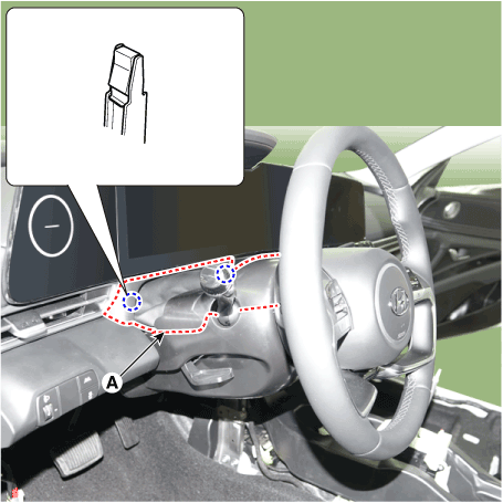
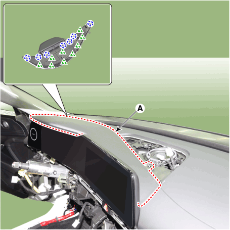
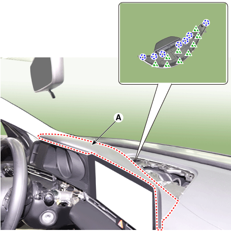
| 2. | When removing with a flat-tip screwdriver or remover, remove the steering column shroud upper panel (A).
|
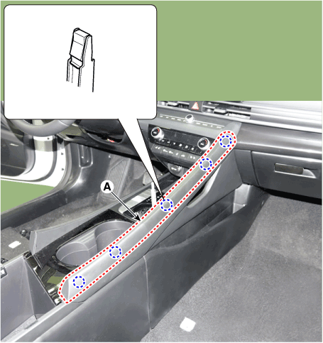
| 3. | When removing with a flat-tip screwdriver or remover, remove the floor console side garnish (A).
|
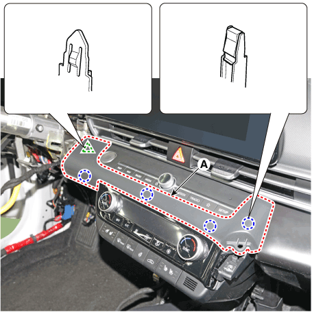
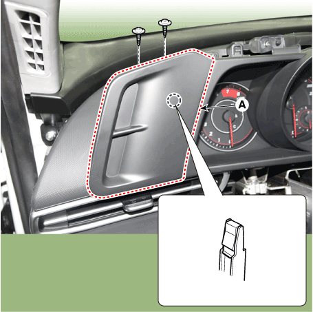
| 4. | When removing with a flat-tip screwdriver or remover, remove the crash pad garnish[CTR] (A).
|
| 5. | Remove the heater & A/C control unit. (Refer to Heating, Ventilation and Air Conditioning - "Heater & A/C Control Unit (DATC)") (Refer to Heating, Ventilation and Air Conditioning - "Heater & A/C Control Unit (Manual)") |
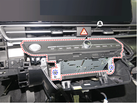
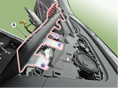
| 6. | Remove the AVN head unit (A) after loosening mounting screws.
|
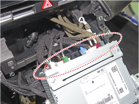
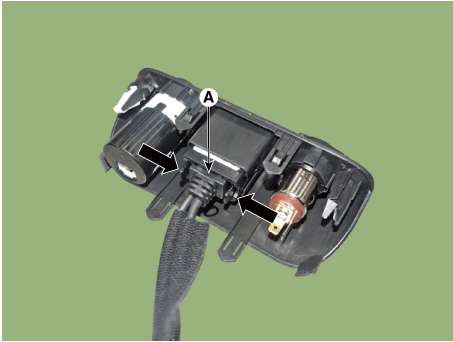
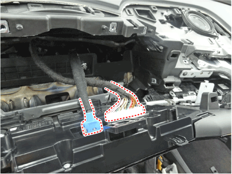
| 7. | Remove the AVN head unit connectors and cables (A).
|
| Installation |
| 1. | Install the AVN head unit. |
| 2. | Install the heater & A/C control unit. |
| 3. | Install the crash pad garnish[CTR]. |
| 4. | Install the floor console side garnish. |
| 5. | Install the steering column shroud upper panel. |
| 6. | Disconnect the negative (-) battery terminal.
|

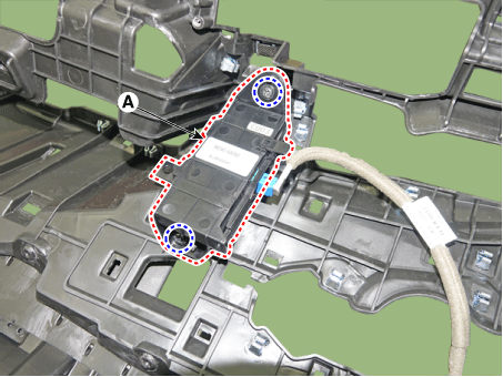
External AMP
Components and components location
| Components |
|
NO
|
Connector A
|
NO
|
Connector B
|
| 1 | BATT (+) | 1 | Subwoofer 2 (+) |
| 2 | BATT (+) | 2 | Subwoofer 1 (+) |
| 3 | BATT (+) | 3 | Sub woofer speaker (+) |
| 4 | BATT (+) | 4 | - |
| 5 | - | 5 | - |
| 6 | Multimedia CAN (High) | 6 | - |
| 7 | Multimedia CAN (Low) | 7 | Navigation voice (+) |
| 8 | ACC | 8 | - |
| 9 | - | 9 | - |
| 10 | - | 10 | - |
| 11 | - | 11 | - |
| 12 | - | 12 | Rear door speaker - RH (+) |
| 13 | - | 13 | Rear door speaker - LH (+) |
| 14 | - | 14 | Center speaker (+) |
| 15 | - | 15 | - |
| 16 | Ground | 16 | Front door tweeter speaker - RH (-) |
| 17 | Ground | 17 | Front door tweeter speaker - LH (-) |
| 18 | Ground | 18 | Sub woofer speaker (-) |
| 19 | Ground | 19 | - |
| 20 | SPDIF (High) | 20 | - |
| 21 | SPDIF (Low) | 21 | Navigation voice (+) |
| 22 | SPDIF GND | 22 | - |
| 23 | - | 23 | - |
| 24 | IGN 1 | 24 | - |
| 25 | - | 25 | Rear door speaker - RH (-) |
| 26 | - | 26 | Rear door speaker - LH (-) |
| 27 | - | 27 | Center speaker (+) |
| 28 | - | 28 | - |
Repair procedures
| Removal |
| 1. | Disconnect the negative (-) battery terminal. |
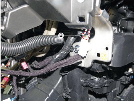
| 2. | Open the trunk, remove the right luggage side trim. (Refer to Body - "Luggage Side Trim") |
| 3. | Remove the external amplifier (B) after disconneting the connector (A) and loosening the mounting nuts.
|
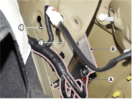
| Installation |
| 1. | Install the external amplifier after connecting the connector. |
| 2. | Install the right luggage side trim. |
| 3. | Connect the negative (-) battery terminal.
|
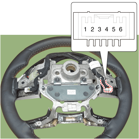
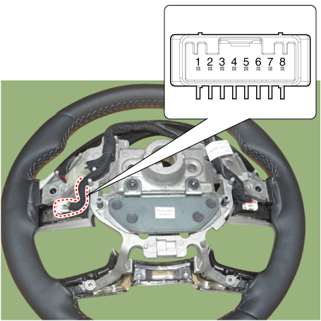
AVN Remote Controller
Components and components location
| Components |
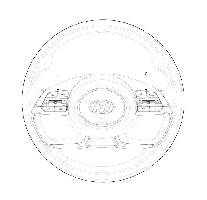
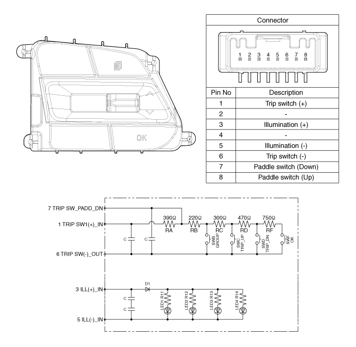
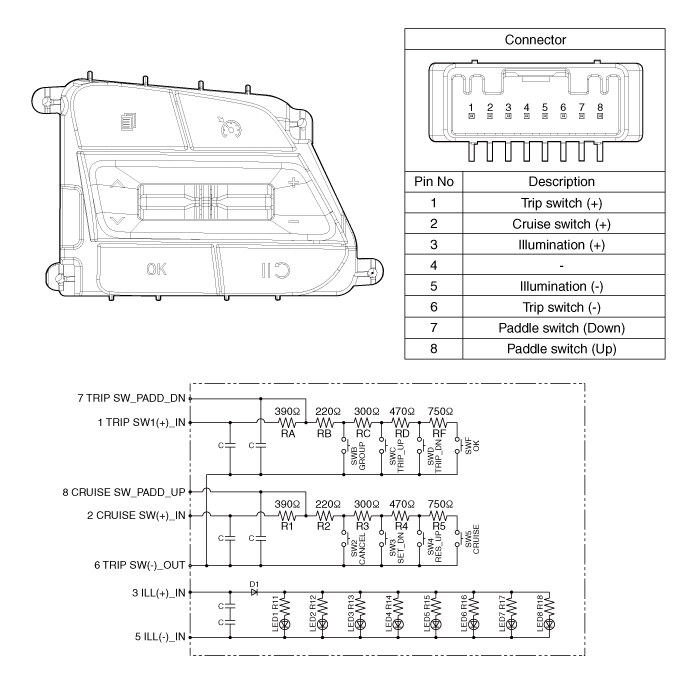
| 1. Left Remote Control Switch (Audio + Bluetooth) | 2. Right Remote Control Switch (Cruise + Trip) |
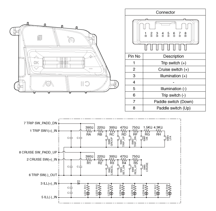
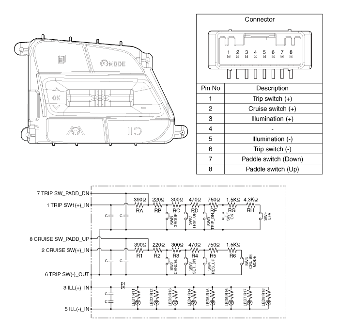
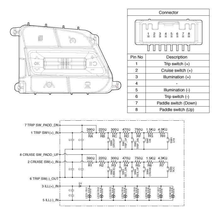
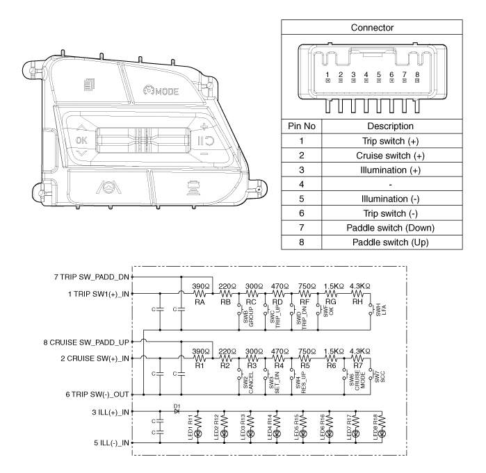
Schematic diagrams
| Circuit Diagram |
| [Without paddle shift] |
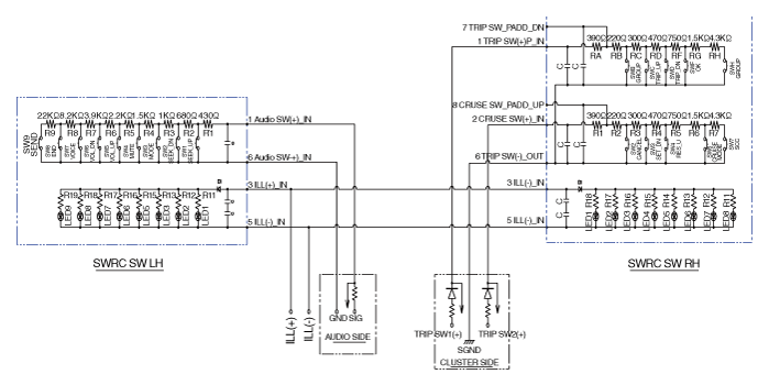
| [With paddle shift] |
[Audio + B/Tooth]
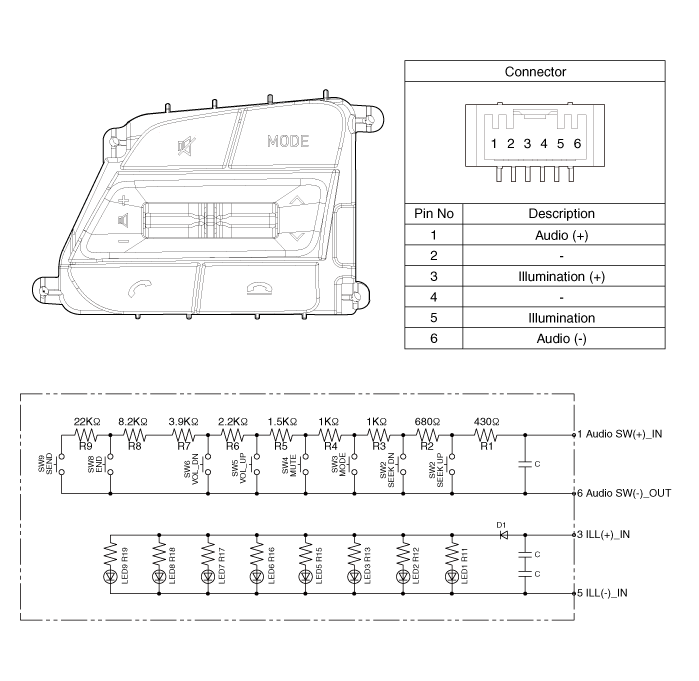
[Audio + B/Tooth + Voice]

[Trip]
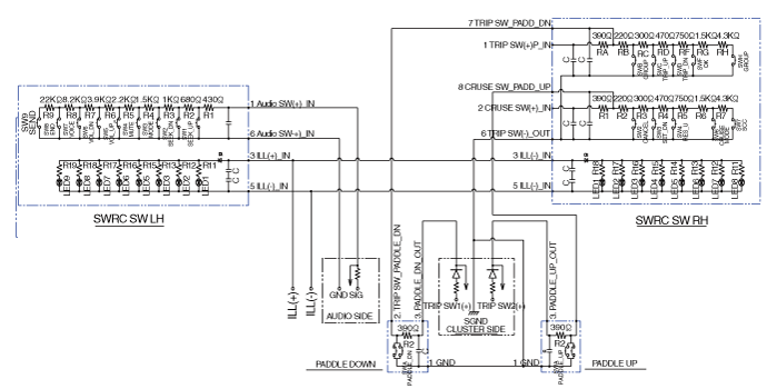
[Trip / Cruise]
[Trip + Cruise + LFA)
[Trip + Cruise + LFA + MSLA)
[Trip + Smart Cruise + LFA)
[Trip + Smart Cruise + LFA + MSLA)
Repair procedures
| Inspection |
| 1. | Check for resistance between terminals in each switch position (LH).
[LH : Audio + Hands free]
|
| 2. | Check for resistance between terminals in each switch position (RH).
[Cruise]
[Trip]
|
| Removal |
| 1. | Disconnect the negative (-) battery terminal. |
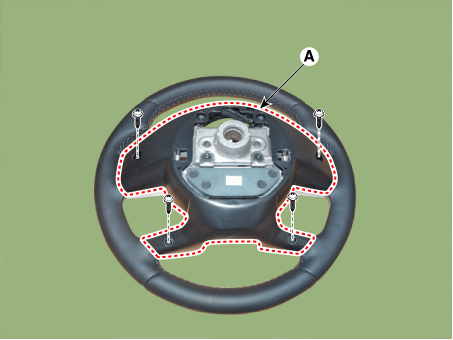
| 2. | Remove the steering wheel assembly. (Refer to Steering System - "Steering Wheel") |
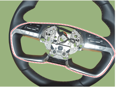
| 3. | Remove the steering back cover (A).
|
| 4. | Remove the steering remote control connector (A).
|
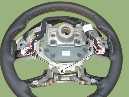
| 5. | Remove the steering remote control switch (A) after loosening the screws.
|
| Installation |
| 1. | Install the steering wheel remote control after connecting the connector. |
| 2. | Install the steering wheel. |
| 3. | Connect the negative (-) battery terminal. |
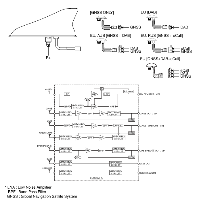
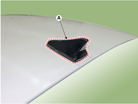
AVN Antenna
Components and components location
| Components |
Repair procedures
| Removal |
Roof Antenna
| 1. | Disconnect the negative (-) battery terminal. |
| 2. | Remove the roof trim. (Refer to Body - "Roof Trim Assembly") |
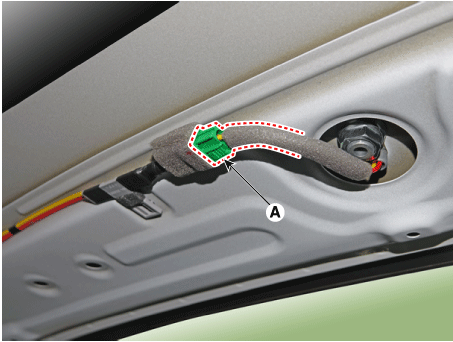
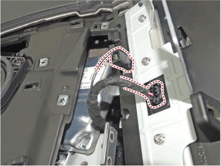
| 3. | Disconnect the roof antenna connector (A).
|
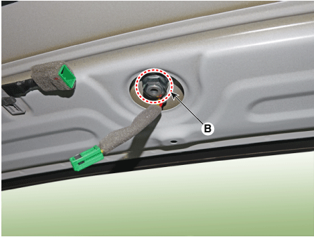
| 4. | Remove the roof antenna (A) after loosening a nut (B).
|
Crash Pad Antenna
| 1. | Disconnect the negative (-) battery terminal. |
| 2. | Remove the main crash pad assembly. (Refer to Body - "Main Crash Pad Assembly") |
| 3. | Loosen the mounting screws and then remove the crash pad antenna (A).
|
| Installation |
Roof Anenna
| 1. | Connect the roof antenna connectors. |
| 2. | Install the roof trim assembly.
|
Crash Pad Antenna
| 1. | Connect the roof antenna connectors and install the roof antenna. |
| 2. | Install the main crash pad assembly. |
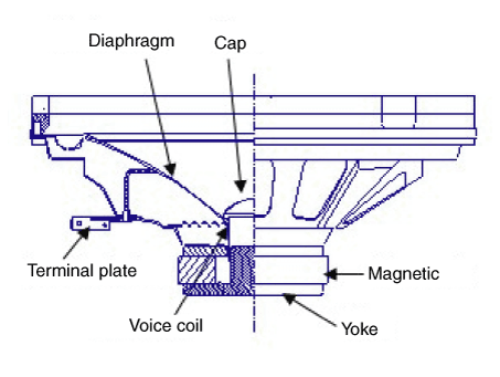
Speaker
Repair procedures
| Inspection |
| 1. | Troubleshooting for Speaker
|
| Removal |
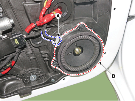
[Front Door Speakers]
| 1. | Disconnect the negative (-) battery terminal. |
| 2. | Remove the front door trim. (Refer to Body - "Front Door Trim") |
| 3. | Remove the front door speaker (B) after disconnecting the connector (A) and loosening screws.
|
[Front Door Tweeter Speaker]
| 1. | Disconnect the negative (-) battery terminal. |
| 2. | Remove the front door trim. (Refer to Body - "Front Door Trim") |
| 3. | Remove the tweeter speaker (A) after loosening screws.
|
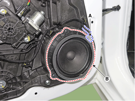
[Rear Door Speakers ]
| 1. | Disconnect the negative (-) battery terminal. |
| 2. | Remove the Rear door trim. (Refer to Body - "Rear Door Trim") |
| 3. | Remove the rear door speaker (B) after disconnecting the connector (A) and loosening screws.
|
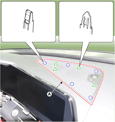
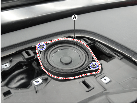
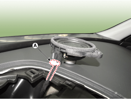
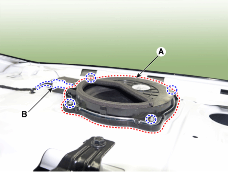
[Crash Pad Center Speaker]
|
| 1. | Using a screwdriver or remover, remove the crash pad center speaker grille (A).
|
| 2. | Remove the center speaker (A) after loosening screws.
|
| 3. | Disconnect the speaker connector (A).
|
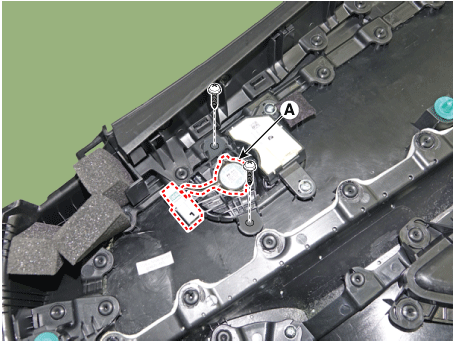
[Sub Woofer Speaker]
| 1. | Remove the rear seat. (Refer to Body - "Rear Seat") |
| 2. | Remove the package tray trim. (Refer to Body - "Rear Package Tray Trim") |
| 3. | Remove the sub woofer speaker (A) after disconnect the connector(B) and loosening the bolts.
|
| Installation |
Front Door Speaker
| 1. | Install the front door speaker. |
| 2. | Install the front door trim. |
Rear Door Speaker
| 1. | Install the rear door speaker. |
| 2. | Install the rear door trim. |
Crash Pad Center Speaker
| 1. | Install the center speaker. |
| 2. | Install the center speaker grille. |
Subwoofer Speaker
| 1. | Install the subwoofer speaker. |
| 2. | Install the rear package tray and rear seat. |
|
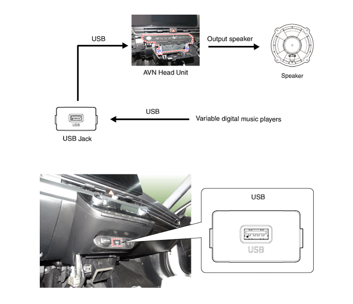
USB Jack
Description and operation
| Description |
The multimedia jack on the console upper cover is for customers who like to listen to external portable music players like the MP3 etc., through the vehicle's sound system when it is linked to this jack. The customer has this added option.
In case of distortions from media connected to the AUX source, the audio unit may not be defective but the output level of the used media does not match the specification of the AUX input.
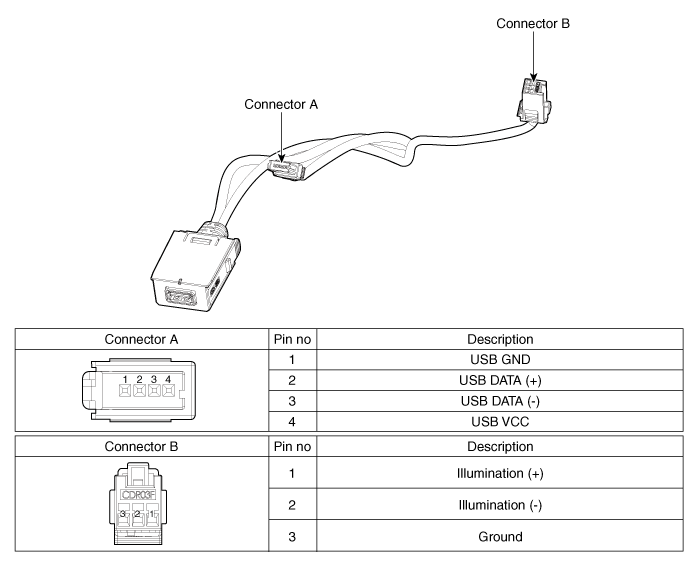
Schematic diagrams
| Circuit Diagram |
Repair procedures
| Removal |
| 1. | Disconnect the battery (-) terminals. |
| 2. | Remove the floor console assembly. (Refer to Body - "Floor Console Assembly") |
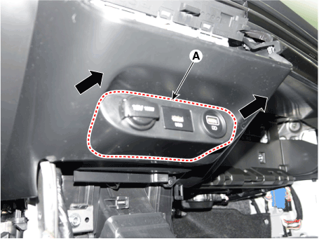
| 3. | Remove the UBS port assembly (A).
|
| 4. | Remove the avn head unit. (Refer to AVN System - "AVN(Audio Video Navigation) head unit") |
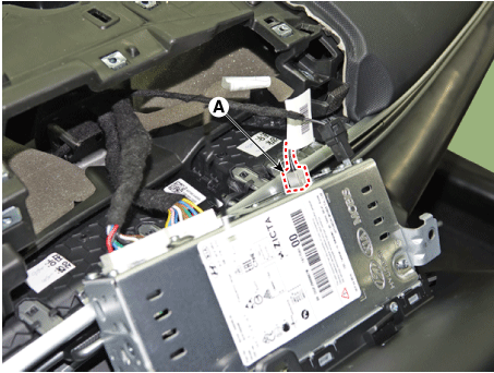
| 5. | Disconect the USB connector (A).
|
| 6. | Disconect the USB connector (B). [Display Audio only]
|
| 7. | Remove the USB jack (A) after releasing the fixed hooks.
|
| Installation |
| 1. | Connect the USB jack connector. |
| 2. | Install the USB jack. |
| 3. | Install the UBS port assembly. |
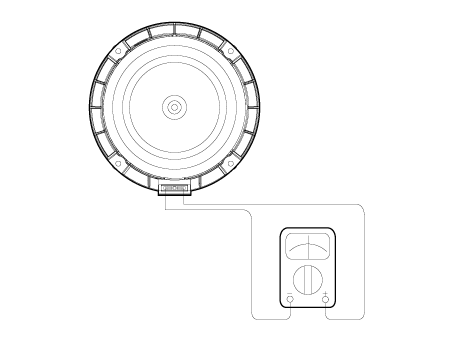
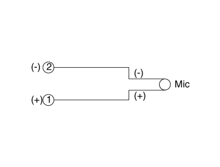
Mic
Repair procedures
| Inspection |
| 1. | Disconnector the negative (-) battery terminal. |
| 2. | Remove the overhead console lamp. (Refer to Body Electrical System - "Overhead Console Lamp") |
| 3. | Remove the overhead console cover after loosening the screws.
|
| 4. | Check the continuity of between terminals.
|
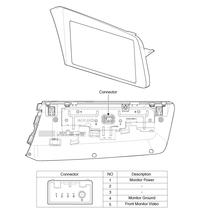
Front monitor
Components and components location
| Components |
Repair procedures
| Removal |
10.25" Cluster + 10.25" Monitor
|
| 1. | Disconnect the negative (-) battery terminal. |
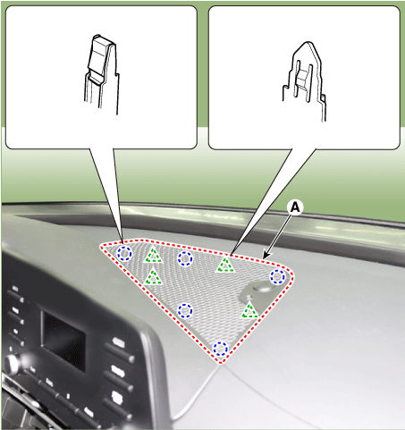
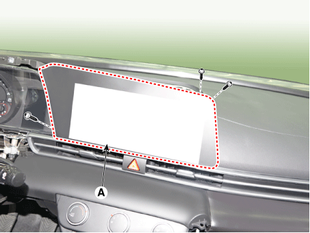
| 2. | Using a flat-tip screwdriver or remover, remove the photo sensor cover (A).
|
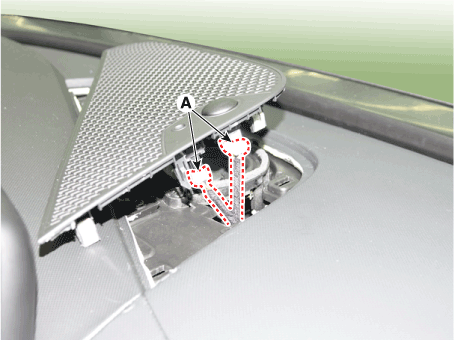
| 3. | Disconnect photo sensor connector and security sensor connector (A).
|
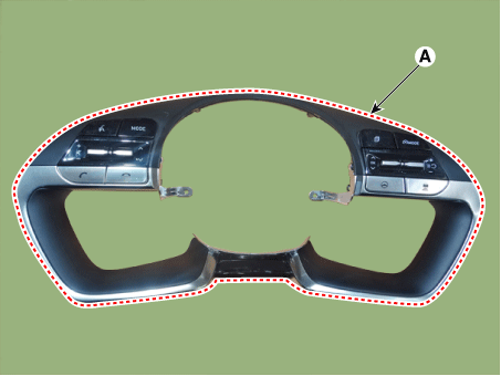
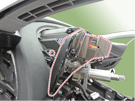
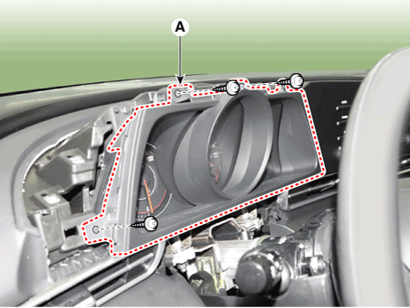
| 4. | Using a flat-tip screwdriver or remover, remove the cluster fascia upper garnish (A).
|
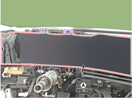
| 5. | Remove the AVN monitor (A) after loosening mounting screws.
|
| 6. | Remove the AVN monitor after disconnecting cluster connectors and monitor connectors.
|
4.25" Cluster + 10.25" Monitor
| 1. | Disconnect the negative (-) battery terminal. |
| 2. | Using a flat-tip screwdriver or remover, remove the photo sensor cover (A).
|
| 3. | Disconnect photo sensor connector and security sensor connector (A).
|
| 4. | Using a flat-tip screwdriver or remover, remove the cluster fascia upper garnish (A).
|
| 5. | Remove the cluster fascia side panel (A).
|
| 6. | Remove the cluster fascia panel (A) after loosening mounting screws.
|
| 7. | Remove the AVN monitor (A) after loosening mounting screws.
|
| 8. | Remove the AVN monitor after disconnecting monitor connectors.
|
| Installation |
10.25" Cluster + 10.25" Monitor
| 1. | Install the AVN monitor after connecting cluster connectors and monitor connectors. |
| 2. | Install the cluster fascia upper garnish. |
| 3. | Install photo sensor cover. |
| 4. | Connect the negative (-) battery terminal.
|
4.25" Cluster + 10.25" Monitor
| 1. | Install the AVN monitor after connecting cluster connectors and monitor connectors. |
| 2. | Install the cluster fascia panel. |
| 3. | Install the cluster fascia side panel. |
| 4. | Install the cluster fascia upper garnish. |
| 5. | Install photo sensor cover. |
| 6. | Connect the negative (-) battery terminal.
|


