 Hyundai Elantra CN7: SRSCM
Components and components location
| Components |
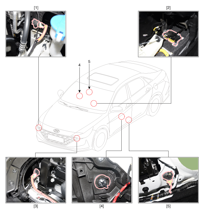
| 1. Front impact sensor (FIS) 2. Supplemental Restraint System Control Module (SRSCM) 3. Front impact sensor (FIS) | 4. Gravity side Impact Sensor (G-SIS) 5. Pressure Side Impact Sensor (P-SIS) |
SRS Control Module (SRSCM)
Description and operation
| Description |
| • | Supplemental Restraint System Control Module (SRSCM) determines whether and when to deploy air bag module, seat belt pretensioner (BPT). |
| • | It supplies the air bag module with the power required to deploy the module or the BPT. |
| • | It also performs self-diagnosis function of the supplemental restraint system. |
Components and components location
| Components |
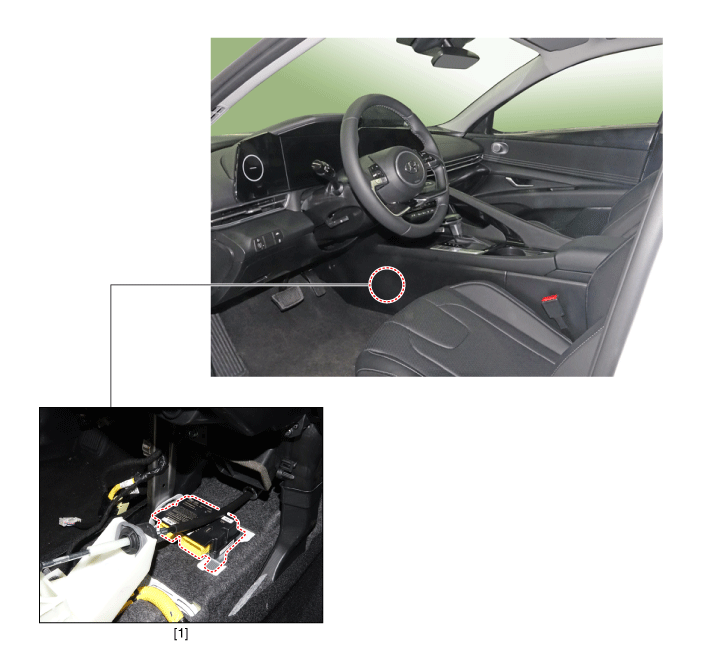
| 1. Supplemental Restraint System Control Module (SRSCM) |
Supplemental Restraint System Control Module (SRSCM)
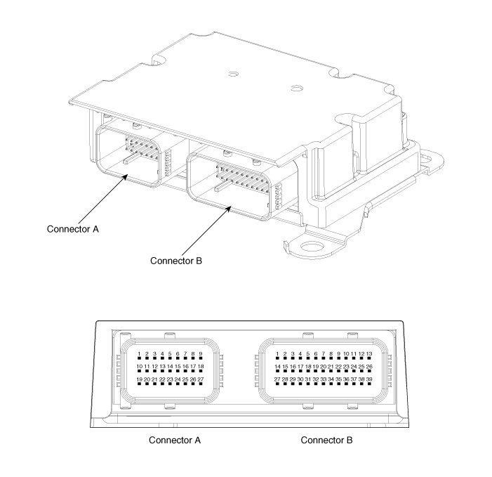
|
No
|
Connector A
|
Connector B
|
| 1 | IGN 1 | Ground |
| 2 | Driver front impact sensor - High (+) | Driver seat belt pretensioner - High (+) |
| 3 | Driver front impact sensor - Low (-) | Driver seat belt pretensioner - Low (-) |
| 4 | Driver airbag 1st stage - High (+) | Driver adapted road limiter - High (+) |
| 5 | Driver airbag 1st stage - Low (-) | Driver adapted road limiter - Low (-) |
| 6 | Passenger airbag 1st stage - Low (-) | Driver side airbag - High (+) |
| 7 | Passenger airbag 1st stage - High (+) | Driver side airbag - Low (-) |
| 8 | - | Passenger side airbag - Low (-) |
| 9 | - | Passenger side airbag - High (+) |
| 10 | Crash signal output | Driver side impact sensor - High (+) |
| 11 | Passenger front impact sensor - High (+) | Driver side impact sensor - Low (-) |
| 12 | Passenger front impact sensor - Low (-) | Passenger side impact sensor - Low (-) |
| 13 | Driver airbag 2nd stage - High (+) | Passenger side impact sensor - High (+) |
| 14 | Driver airbag 2nd stage - Low (-) | Passenger seat belt buckle sensor - High (+) |
| 15 | Passenger airbag 2nd stage - Low (-) | Passenger seat belt pretensioner - High (+) |
| 16 | Passenger airbag 2nd stage - High (+) | Passenger seat belt pretensioner - Low (-) |
| 17 | C-CAN (High) | - |
| 18 | C-CAN (Low) | - |
| 19 | B + | Driver curtain airbag - High (+) |
| 20 | Passenger airbag OFF lamp | Driver curtain airbag - Low (-) |
| 21 | - | Passenger curtain airbag - Low (-) |
| 22 | - | Passenger curtain airbag - High (+) |
| 23 | - | Driver Passenger side impact sensor - High (+) |
| 24 | - | Driver pressure side impact sensor - Low (-) |
| 25 | - | Passenger pressure side impact sensor - Low (-) |
| 26 | Local CAN (High) | Passenger Passenger side impact sensor - High (+) |
| 27 | Local CAN (Low) | Driver seat belt buckle sensor - High (+) |
| 28 | Driver rear seat belt pretensioner - High (+) | |
| 29 | Driver rear seat belt pretensioner - Low (-) | |
| 30 | Passenger rear seat belt pretensioner - High (+) | |
| 31 | Passenger rear seat belt pretensioner - Low (-) | |
| 32 | - | |
| 33 | - | |
| 34 | - | |
| 35 | - | |
| 36 | - | |
| 37 | - | |
| 38 | - | |
| 39 | - |
Repair procedures
| Removal |
| 1. | Turn the ignition switch OFF and disconnect the battery negative (-) cable.
|
| 2. | Remove the floor console assembly. (Refer to Body - "Floor Console Assembly") |
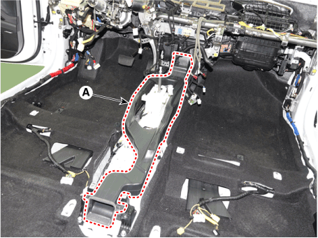
| 3. | Remove the center console duct (A).
|
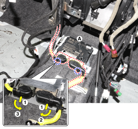
| 4. | Pull up the lock of the SRSCM connector to disconnect the connector (A).
|
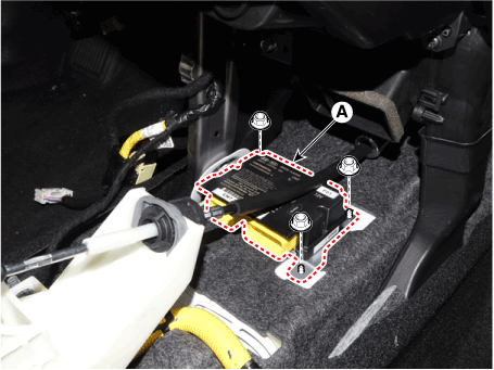
| 5. | Remove the SRSCM (A) after loosening the mounting nuts.
|
| Installation |
| 1. | Check if the battery (-) cable is disconnected.
|
| 2. | Install the SRSCM (A) with the SRSCM mounting nuts.
|
| 3. | Connect the SRSCM harness connector. |
| 4. | Install the heater ducts and floor console. (Refer to Body - "Floor Console Assembly") |
| 5. | Reconnect the battery negative cable. |
| 6. | After installing the SRSCM, confirm proper system operation :
|
| Adjustment |
[Variant Coding]
| 1. | Connect the cable of diagnostic tool to the data link connector in driver side crash pad lower panel, and turn on the diagnostic tool. |
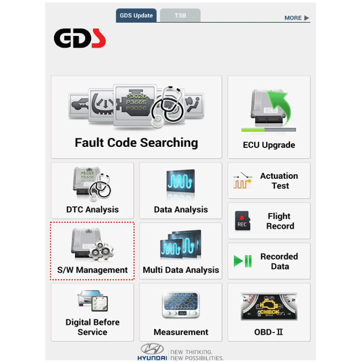
| 2. | Select the 'S/W Management' and 'Car model'.
|
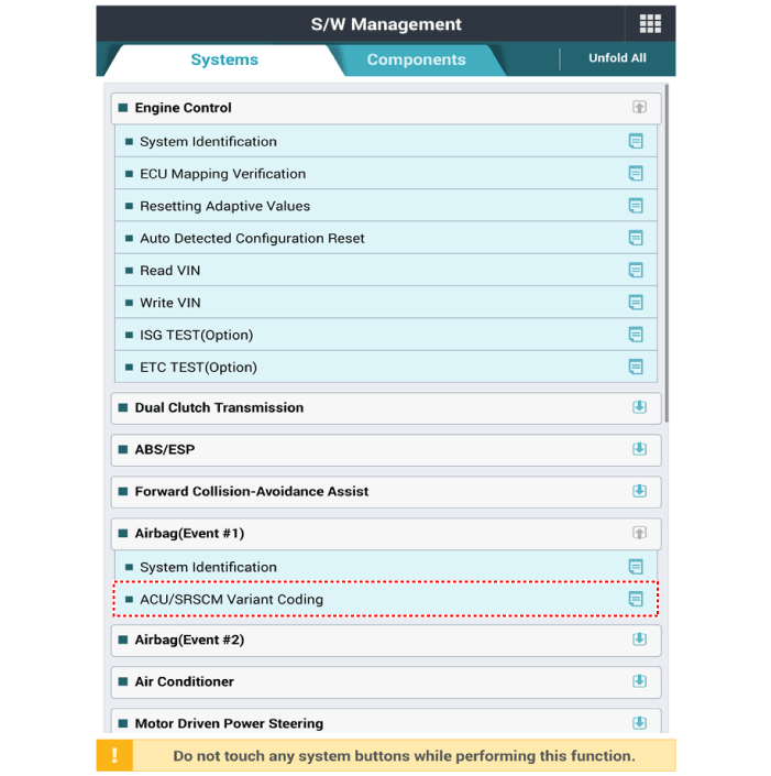
| 3. | Select "Airbag" and "ACU/SRSCM Variant Coding".
|
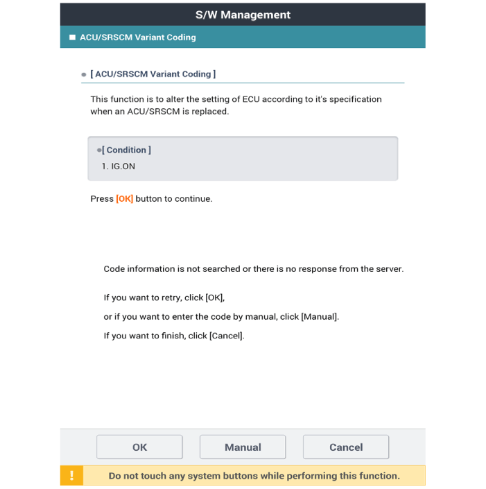
| 4. | Perform the "ACU/SRSCM Variant Coding" procedure according to the GDS screen message.
|
[Longitudinal G Sensor Calibration]
| 1. | Connect the cable of diagnostic tool to the data link connector in driver side crash pad lower panel, and turn on the diagnostic tool. |
| 2. | Select the 'S/W Management' and 'Car model'.
|
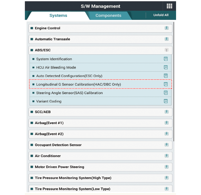
| 3. | Select "Longitudinal G Sensor Calibration".
|
Front Impact Sensor (FIS)
Description and operation
| Description |
The front impact sensor (FIS) is installed in the Front End Module (FEM). They are remote sensors that detect acceleration due to a collision at its mounting location.
The primary purpose of the Front Impact Sensor (FIS) is to provide an indication of a collision. The Front Impact Sensor (FIS) sends acceleration data to the SRSCM.
Components and components location
| Components |
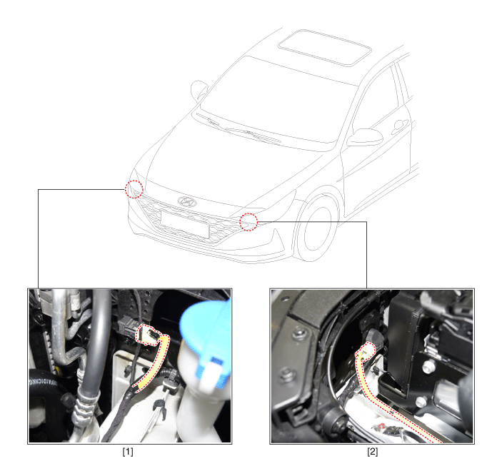
| 1. Passenger front impact sensor (FIS) | 2. Driver front impact sensor (FIS) |
Repair procedures
| Removal |
| 1. | Disconnect the negative (-) battery terminal.
|
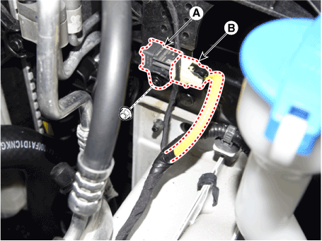
| 2. | Disconnect the front impact sensor connector (B) and then remove the front impact sensor (A) after loosening the mounting bolt. [LH]
[RH]
|
| Installation |
| 1. | Check if the battery (-) cable is disconnected.
|
| 2. | Install a new front impact sensor and connect the front impact sensor connector. |
| 3. | Tighten the front impact sensor mounting bolt.
|
| 4. | Reconnect the battery negative (-) terminal. |
| 5. | After installing the front impact sensor, confirm proper system operation.
|
Side Impact Sensor (SIS)
Description and operation
| Description |
| • | Side Impact Sensors (SIS), each installed on the center part of the right and left front door modules and the right and left center pillars, detects side impact during collision. |
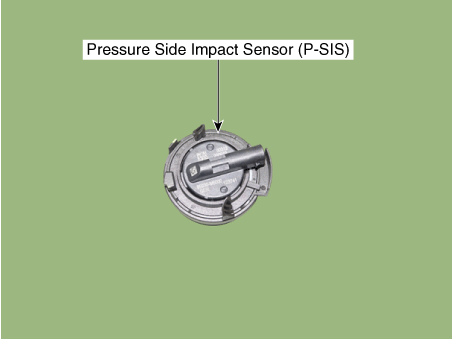
| • | The pressure-sensitive side collision detection sensor (P-SIS) is a method that senses the pressure when it collides, and is also called P-SIS, and the side collision detection sensor (G-SIS) is a method that senses the acceleration at the time of collision. Also called G-SIS. |
| • | The SRSCM uses the signals from SIS during side collision to determine whether and when to deploy the side air bag. |
Components and components location
| Components |
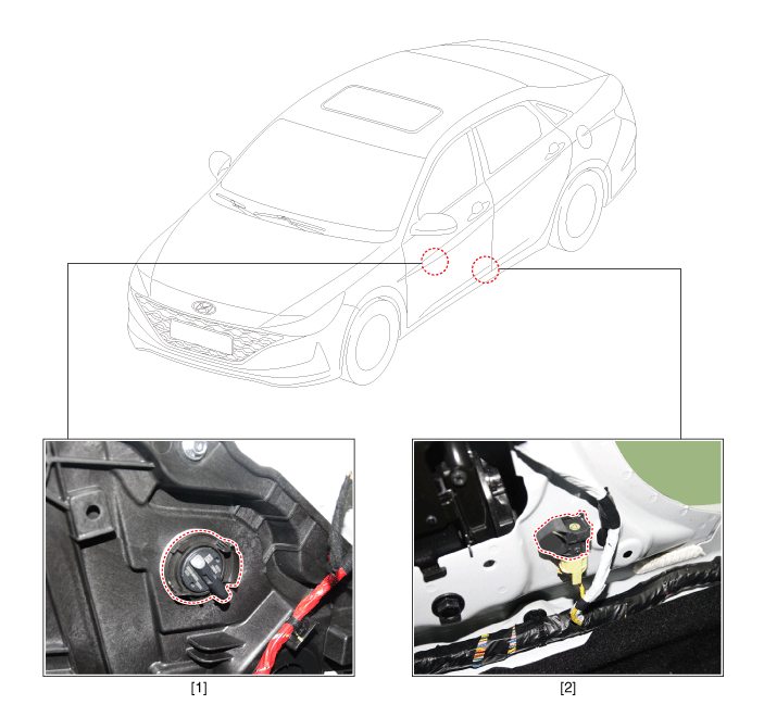
| 1. Pressure Side Impact Sensor (P-SIS) | 2. Gravity Side Impact Sensor (G-SIS) |
Repair procedures
| Removal |
Pressure Side Impact Sensor (P-SIS)
| 1. | Disconnect the negative (-) battery terminal.
|
| 2. | Remove the front door trim. (Refer to Body - "Front Door Trim") |
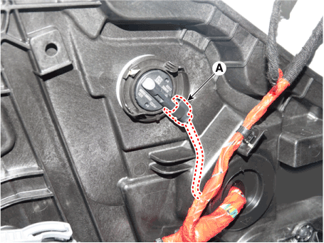
| 3. | Disconnect the pressure side impact sensor connector (A) after pushing the lock pin.
|
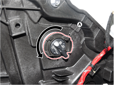
| 4. | Remove the pressure side impact sensor (A) after rotating it in the direction of the arrow.
|
Gravity Side Impact Sensor (G-SIS)
| 1. | Disconnect the negative (-) battery terminal.
|
| 2. | Remove the center pillar trim. (Refer to Body (Interior and Exterior) - "Center Pillar Trim") |
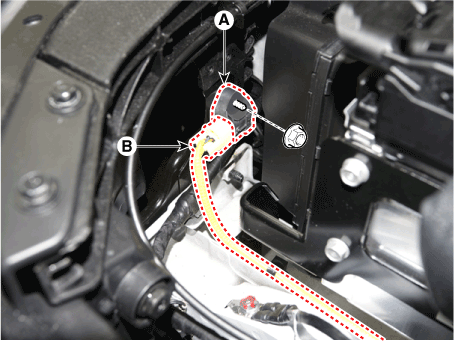
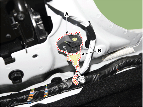
| 3. | Remove the gravity side impact sensor (A) after loosening the mounting bolt and disconnecting the connector (B).
|
| Installation |
Pressure Side Impact Sensor (P-SIS)
| 1. | Check if the battery (-) cable is disconnected.
|
| 2. | Install a new pressure side impact sensor and connect the pressure side impact sensor connector. |
| 3. | Install the front door trim. (Refer to Body - "Front Door Trim") |
| 4. | Reconnect the battery negative (-) terminal. |
| 5. | After installing the front impact sensor, confirm proper system operation.
|
Gravity Side Impact Sensor (G-SIS)
| 1. | Check if the battery (-) cable is disconnected.
|
| 2. | Install the new side impact sensor with the screws, then connect the front side impact sensor connector.
|
| 3. | Install the center pillar trim. (Refer to Body (Interior and Exterior) - "Center Pillar Trim") |
| 4. | Reconnect the battery negative (-) terminal.
|
Seat Belt Buckle Switch (BS)
Description and operation
| Description |
| • | The SRSCM should detect the condition of seat belt buckles (BS) of the driver and passenger seats. |
| • | The SRSCM provides two pins to each side, in order to enter the condition of seat belt buckles (BS) of the driver and passenger seats. |
| • | The seat belt buckle circuit is operated using internal boost voltage supplied by the SRSCM, and uses body ground for signal return. |
Components and components location
| Components |
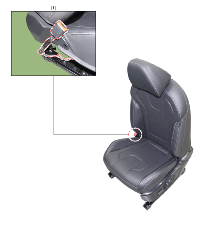
| 1. Seat belt buckle switch (BS) |
Repair procedures
| Removal |
| 1. | Disconnect the negative (-) battery terminal.
|
| 2. | Remove the front seat assembly. (Refer to Body (Interior and Exterior) - "Front Seat Assembly") |
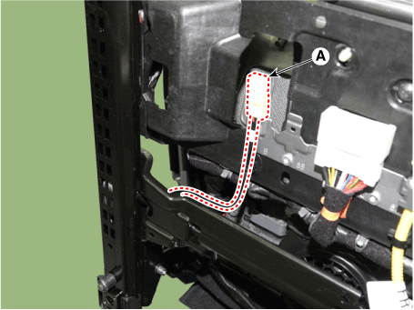
| 3. | Disconnect the front seat belt buckle connector wiring (A).
|
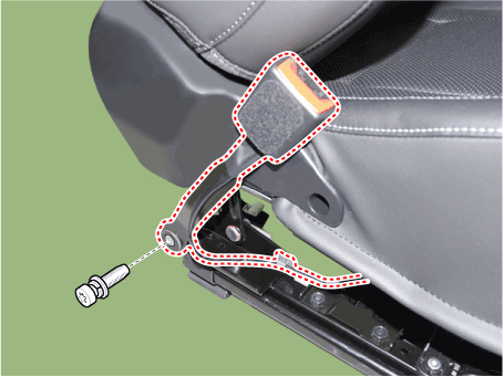
| 4. | Remove the front seat belt buckle (A) after loosening the monuting bolt.
|
| 5. | To install, reverse the removal procedures.
|
Occupant Classification System(OCS)
Description and operation
| Description |
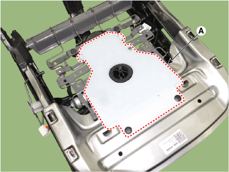
| 1. | In order to make normal activation of airbag system, SRSCM detects DTC(s) for the Occupant Classification System (OCS). If the seat is occupied, OCS detects passenger presences status and send signal to SRSCM via CAN. |
| 2. | SRSCM recognizes the signal as 2(two) different classifications; that is, 1(Empty or small occupant with child restraint system), 2(Occupied with large occupant and small occupant). |
| 3. | With these signal, ACU determines whether it needs to deploy the PAB(Passenger Airbag) or not. |
Components and components location
| Components |
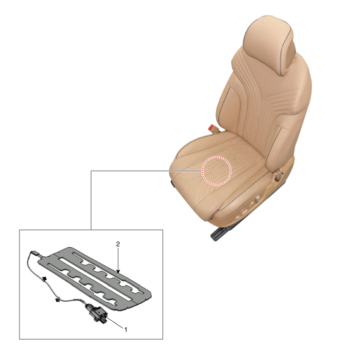
| 1. Occupant Classification System (OCS) Unit | 2. Occupant Classification System (OCS) Sensor |
Occupant Classification Sensor Unit
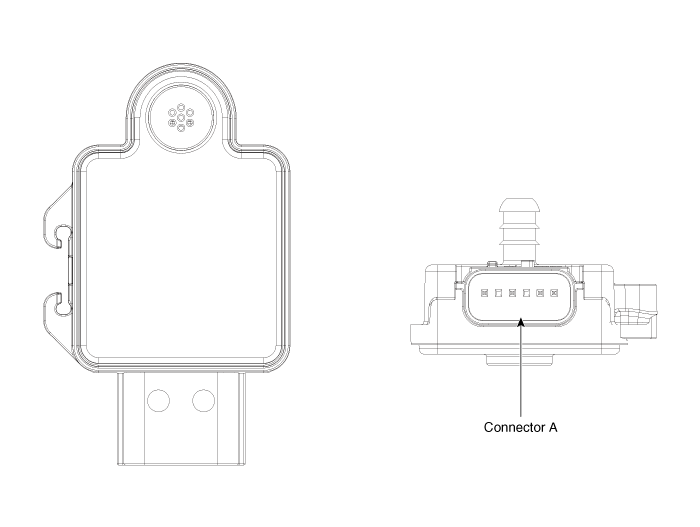

|
Pin no
|
Name
|
| 1 | ALR (-) |
| 2 | ALR (+) |
| 3 | Ground |
| 4 | CAN (Low) |
| 5 | CAN (High) |
| 6 | IGN1 |
Repair procedures
| Removal |
Occupant Classification System (OCS)
| 1. | Disconnect the negative (-) battery terminal.
|
| 2. | Remove the passenger's side front seat assembly. (Refer to Body (Interior and Exterior) - "Front Seat Assembly") |
| 3. | Remove the passenger seat cushion assembly. (Refer to Body (Interior and Exterior) - "Front Seat Cushion Cover") |
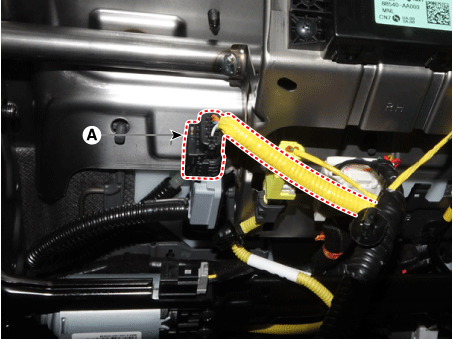
| 4. | Disconnect occupant classification sensor unit connector (A).
|
| 5. | Remove the occupant classification sensor unit (A) after removing the clip.
|
| Installation |
Occupant Classification System (OCS)
| 1. | Install the occupant classification sensor unit in the passenger seat track assembly. |
| 2. | Connect the occupant classification sensor unit connector. |
| 3. | Install the passenger seat cushion assembly. (Refer to Body (Interior and Exterior) - "Front Seat Cushion Cover") |
| 4. | Install the passenger's side front seat assembly. (Refer to Body (Interior and Exterior) - "Front Seat Assembly") |
| 5. | Reconnect the battery negative (-) terminal. |
| 6. | After installing the OCS, confirm proper system operation.
[DTC Manual]
|
| Inspection |
OCS Reset procedure
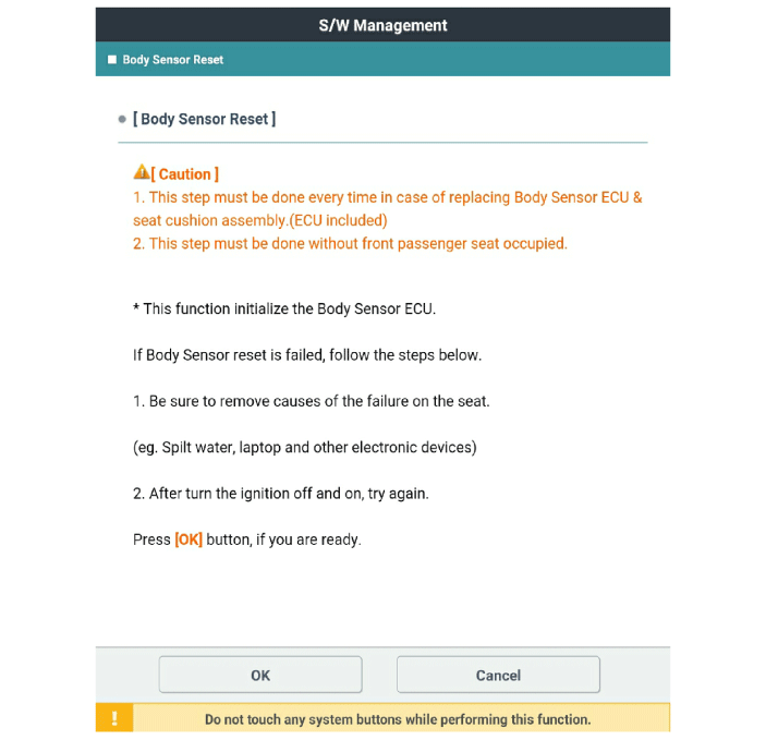
You should perform OCS Reset procedure after service or replacement about all part of the passenger seat. (Not included full seat assembly)
| 1. | Ignition "OFF", connect GDS. |
| 2. | Ignition "ON" & Engine "OFF", select S/W Management and "Car model". |
| 3. | select OCS and "Body Sensor Reset".
|
| 4. | Perform the "Body sensor reset" procedure according to the GDS screen message. |


