 Hyundai Elantra CN7: Power Windows
Description and operation
| Function of Safety Power Window |
When driver door power window auto-up switch is operated, safety function is activated.
| 1. | Safety function condition When detect the force of 100N (using the 10N/mm spring) during the window rising, window is reversed. |
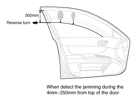
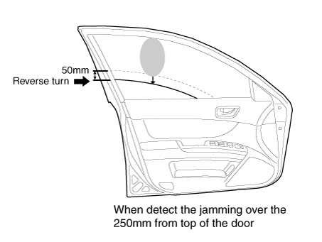
| 2. | Length of window reversing (except holding the auto-up switch)
|
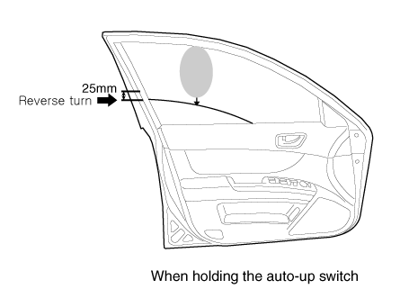
| 3. | Length of window reversing (holding the auto-up switch)
|
| 4. | Safety function is not available area Safety function is not available during the 4mm from top of the door. |
Initializing Method of the Safety Power Window
| 1. | Initializing of Battery Connection When the battery power is removed for over 5 minutes, safety power window switch need the initializing.
|
| 2. | Initializing of fail safe mode
|
Components and components location
| Component Location |
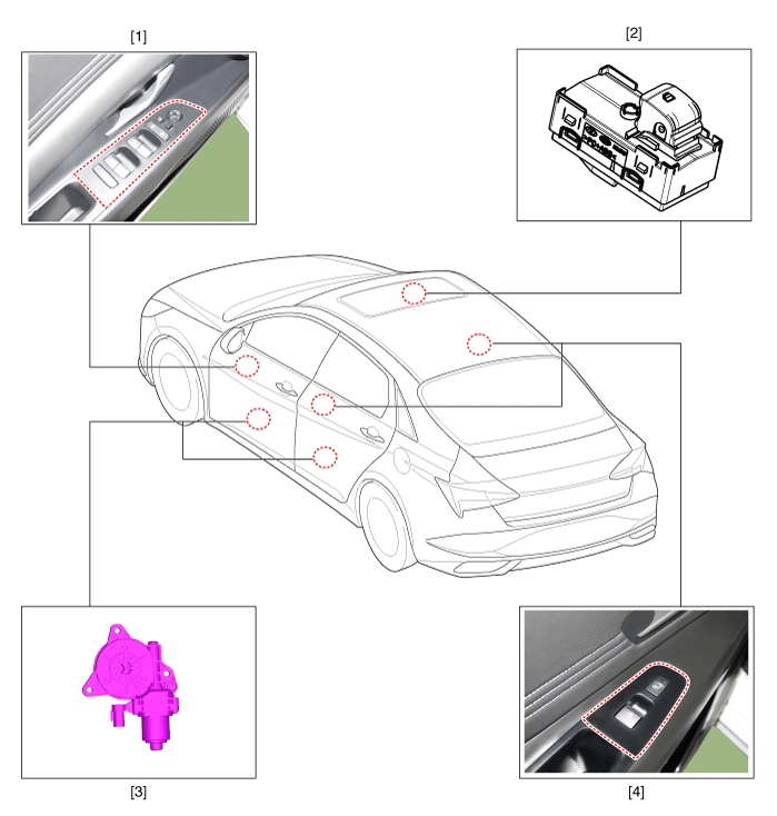
| 1. DDM (Driver Door Module) 2. ADM (Assistant Door Module) | 3. Front/Rear window motor 4. RDM / RLDM (Rear Door Module) |
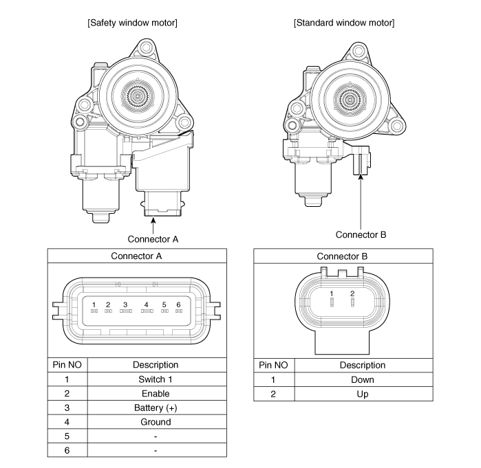
Power Window Motor
Components and components location
| Components |
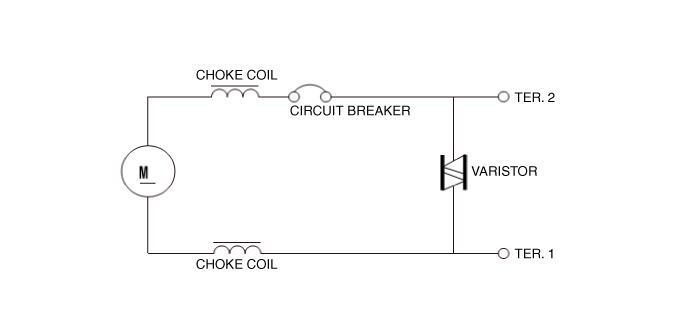
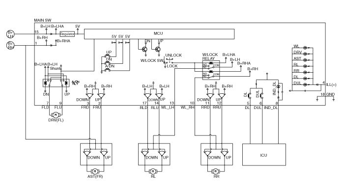
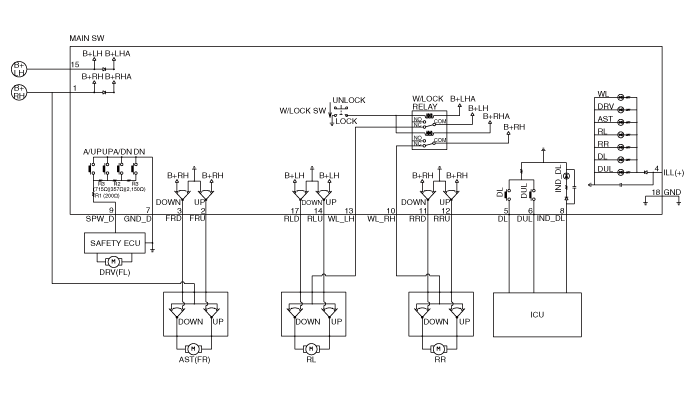
Schematic diagrams
| Circuit Diagram |
Standard type
Repair procedures
| Inspection |
|

Front Power Window Motor
| 1. | Disconnect the negative (-) battery terminal. |
| 2. | Remove the front door trim. (Refer to Body - "Front Door Trim") |
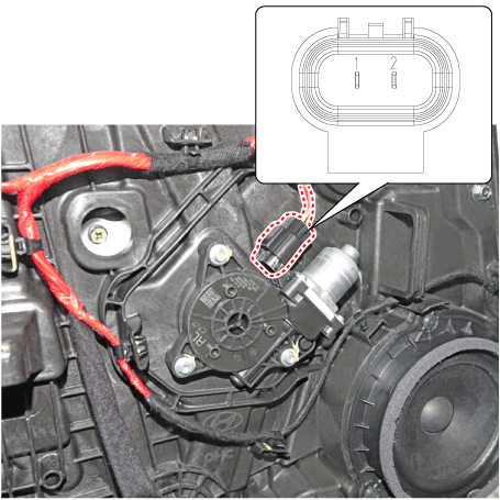
| 3. | Disconnect the motor connector from the motor.
|
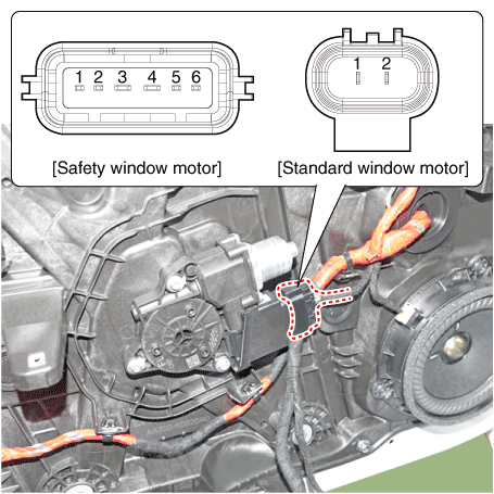
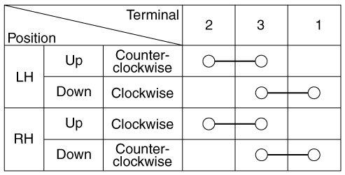
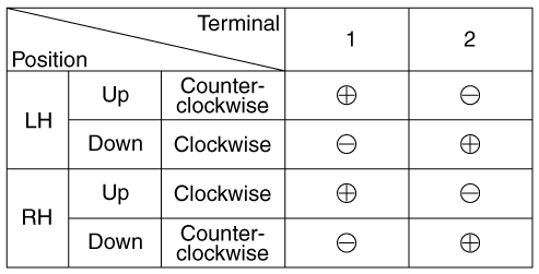
| 4. | Connect the terminal No.1 and No.2 to battery voltage (12V) and check that the motor operates smoothly when connecting the terminals below. [Safety Window Motor]
|
| 5. | Connect the motor terminals directly to battery voltage (12V) and check that the motor operates smoothly. Next, reverse the polarity and check that the motor operates smoothly in the reverse direction. If the operation is abnormal, replace the motor. [Standard Window Motor]
|
Rear Power Window Motor
| 1. | Disconnect the negative (-) battery terminal. |
| 2. | Remove the rear door trim. (Refer to Body - "Rear Door Trim") |
| 3. | Disconnect the motor connector from the motor.
|
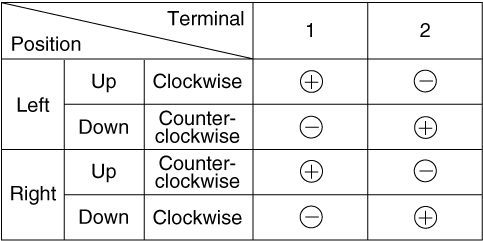
| 4. | Connect the motor terminals No.1 and No.2 directly to battery voltage (12V) and check that the motor operates smoothly. If the operation is abnormal, replace the motor. [Safety Window Motor]
|
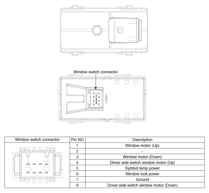
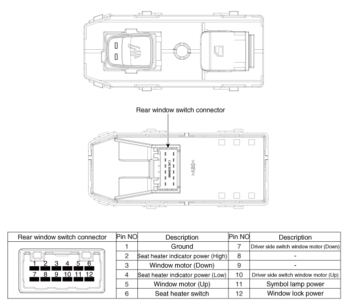
Power Window Switch
Components and components location
| Components |
Driver Power Window Switch
Sub Power Window Switch (Passenger)
Sub Power Window Switch (Rear)
Schematic diagrams
| Circuit Diagram |
Main power window switch
| [Auto down + Door lock] |
| [Driver side safety + Door lock] |
Sub Power Window Switch (Passenger)
Sub Power Window Switch (Rear)
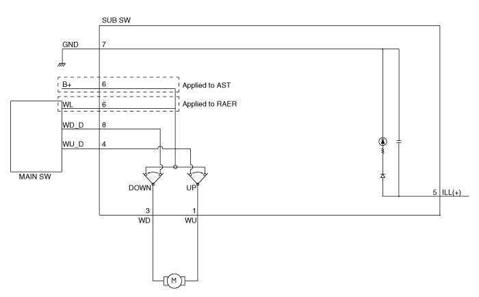
| [Non auto] |
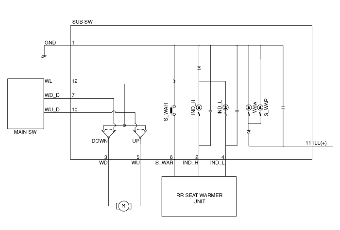
| [Non auto + Seat heater] |
Repair procedures
| Removal |
Driver / Passenger Power Window Switch
| 1. | Disconnect the negative (-) battery terminal. |
| 2. | Remove the front door trim. (Refer to Body - "Front Door Trim") |
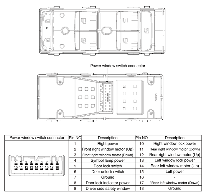
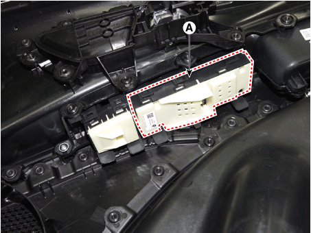
| 3. | Remove the power window switch (A).
|
Rear Power Window Switch
| 1. | Disconnect the negative (-) battery terminal. |
| 2. | Remove the rear door trim. (Refer to Body - "Rear Door Trim") |
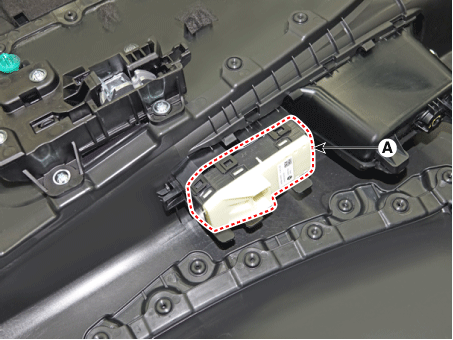
| 3. | Remove the power window switch assembly after disengaging the mounting clips.
|
| Installation |
Driver / Passenger Power Window Switch
| 1. | Install the power window switch assembly. |
| 2. | Install the front door trim after connect the connector. |
Rear Power Window Switch
| 1. | Install the power window switch assembly. |
| 2. | Install the rear power window switch. |


