 Hyundai Elantra CN7: Power Door Locks
Components and components location
| Component Location |
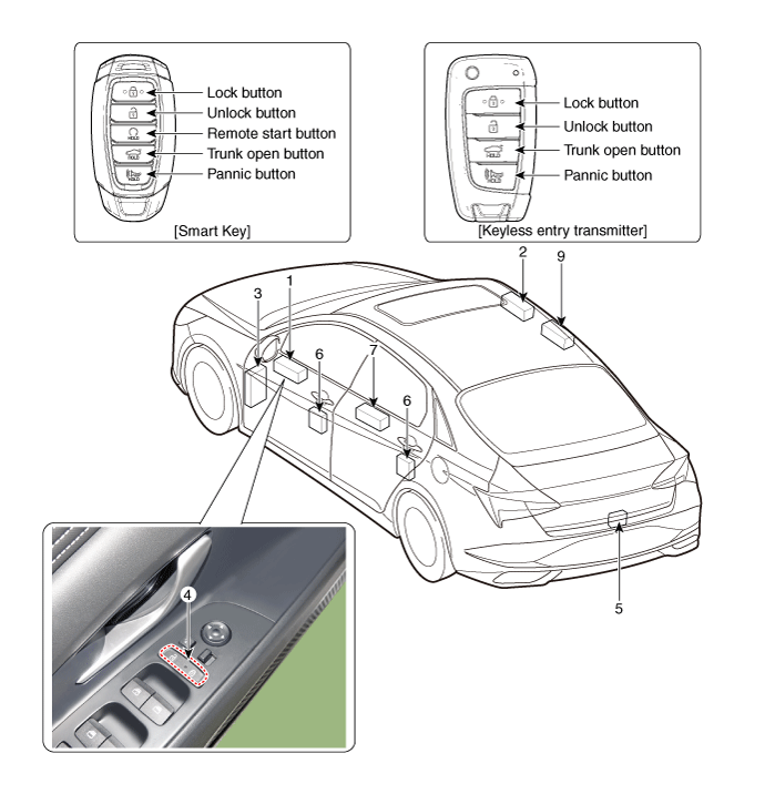
| 1. DDM (Driver Door Module) 2. ADM (Assist Door Module) 3. Integrated Central Control Unit (ICU) 4. Door lock knob 5. Trunk lid actuator | 6. Door latch module 7. Door lock/unlock switch 8. RLDM (Rear Left Door Module) 9. RRDM (Rear Right Door Module) |
Power Door Lock Module
Components and components location
| Conponents |
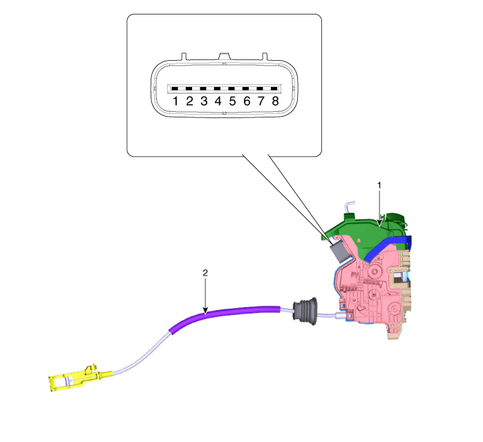
| 1. Door latch assembly | 2. Door latch cable |
Repair procedures
| Inspection |
|

Front Door Lock Module Inspection
| 1. | Remove the front door trim. (Refer to Body - "Front Door Trim") |
| 2. | Remove the front door module. (Refer to Body - "Front Door Module") |
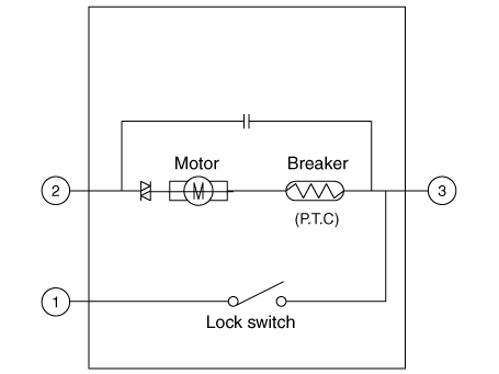
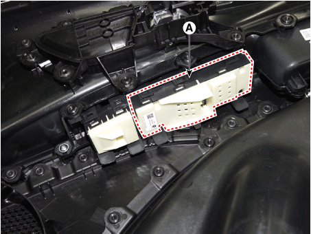
| 3. | Disconnect the connector from the actuator.
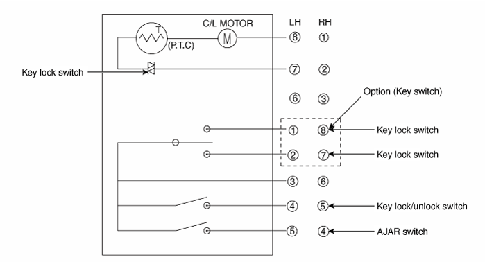
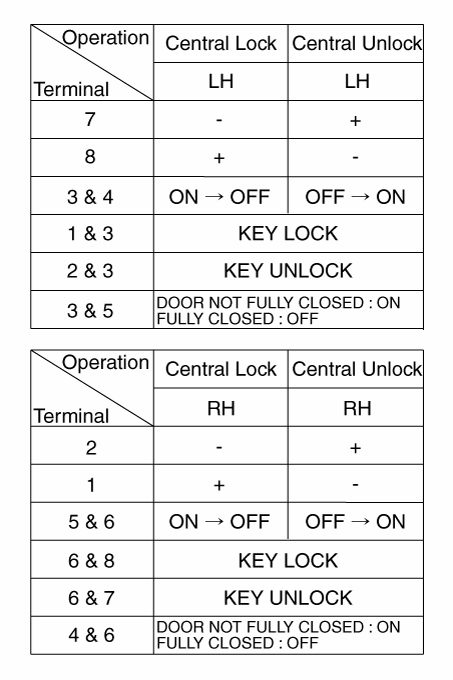
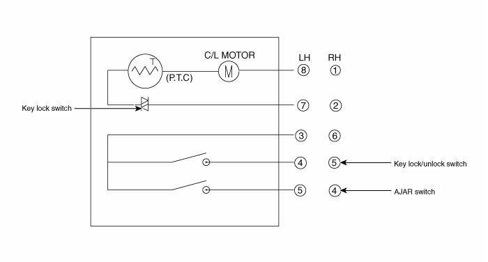
| |||||||||||||||||||||||||||||
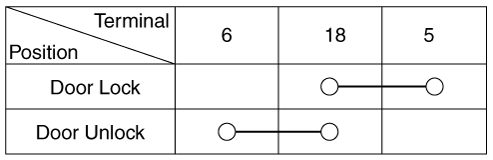
| 4. | Check actuator operation by connecting power and ground according to the table. To prevent damage to the actuator, apply battery voltage only momentarily.
|
Rear Door Lock Module Inspection
| 1. | Remove the rear door trim. (Refer to Body - "Rear Door Trim") |
| 2. | Remove the rear door module. (Refer to Body - "Rear Door Module") |
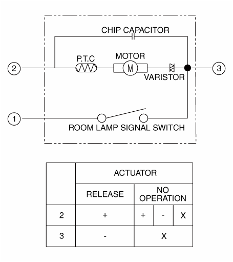
| 3. | Disconnect the connectors from the actuator.
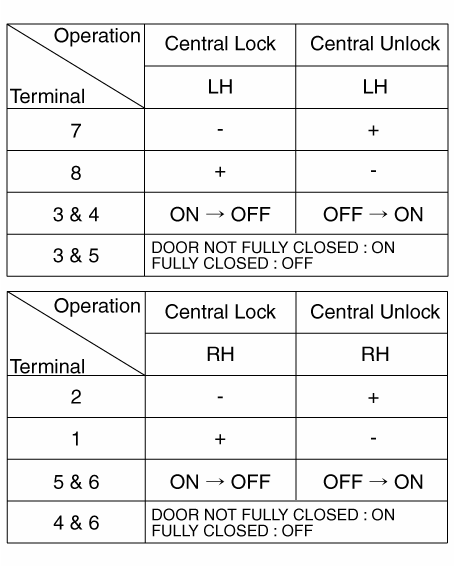
| |||||||||||||||||||||||||||||
| 4. | Check actuator operation by connecting power and ground according to the table. To prevent damage to the actuator, apply battery voltage only momentarily.
|
Tailgate Lock Module Inspection
| 1. | Remove the trunk lid trim. (Refer to Body - "Trunk Lid Trim") |
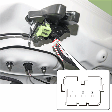
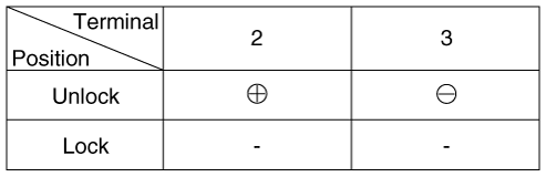
| 2. | Disconnect the connector from the actuator
|
| 3. | Check actuator operation by connecting power and ground according to the table. To prevent damage to the actuator, apply battery voltage only momentarily.
|
| 4. | Checking the trunk of the vehicle power option power refers to the trunk module. |
Power Door Lock Switch
Repair procedures
| Inspection |
Power Door Lock Switch Inspection
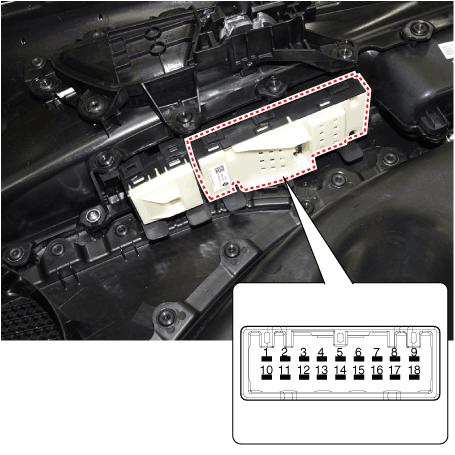
| 1. | Check for continuity between the terminals. If there is an abnormality, replace the switch.
|
| Removal |
|
| 1. | Disconnect the negative (-) battery terminal. |
| 2. | Remove the front door trim. (Refer to Body - "Front Door Trim") |
| 3. | Remove the power window switch assembly after disengaging the mounting clips.
|
| Installation |
| 1. | Install the power window switch assembly. |
| 2. | Install the front door trim after connect the connector. |
| 3. | Connect the negative (-) battery terminal. |


