Heater Unit Components and Components Location
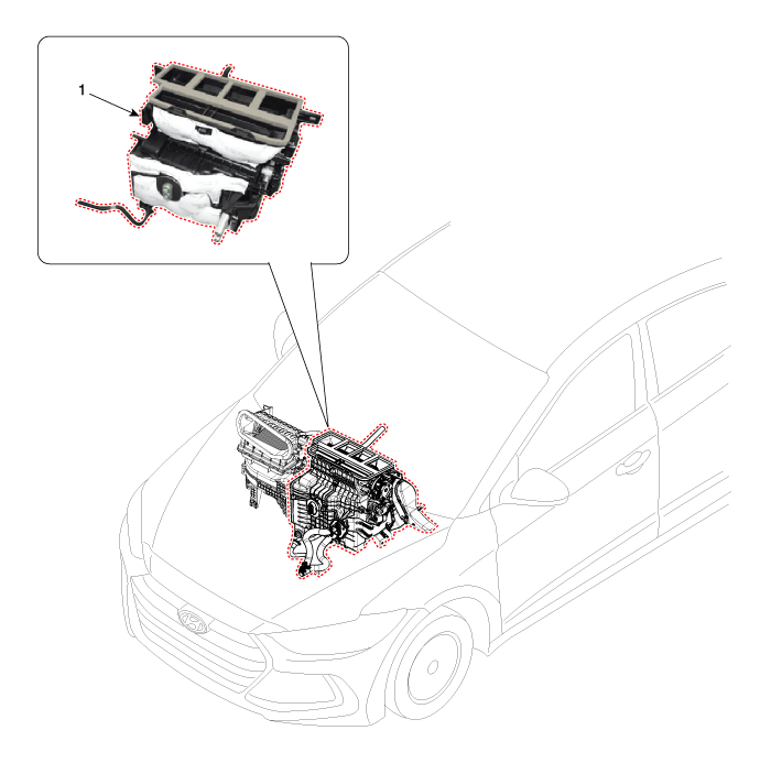

1. Shower duct [LH]
2. Heater core cover
3. Heater core & Seal assembly
4. Mode actuator
5. Temperature control actuator [LH]
6. PTC Heater
7. Heater unit pad
8. Air guide [LH]
9. Heater case [LH]
|
10. Evaporator core assembly
11. Heater core assembly
12. Evaporator lower insulation
13. Separator
14. Heater case [RH]
15. Temperature door assembly
16. Floor door assembly
17. Vent door assembly
18. Deforster door assembly
|
19. Center duct seal
20. Air guide [RH]
21. Auto defogging actuator
22. Hose
23. Temperature control actuator [RH]
24. Evaporator thermistor sub assembly
25. Shower duct [RH]
26. Rear console cover
27. Drain hose
|
Heater Unit Repair procedures
|
When prying with a flat-tip screwdriver or use a prying trim tool, wrap
it with protective tape, and apply protective tape around the related parts,
to prevent damage. |
| 1. |
Disconnect the negative (-) battery
terminal. |
| 2. |
Recover the refrigerant with
a recovery / recycling / charging station. |
| 3. |
When the engine is cool, drain
the engine coolant from the radiator. (Refer to Engine Mechanical System
- "Coolant")
|
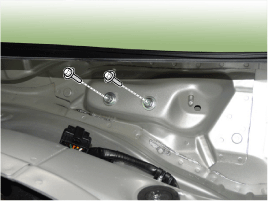
| 4. |
Remove the cowl top cover.
(Refer to Body - "Cowl Top Cover")
|
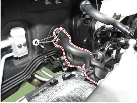
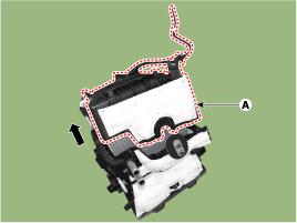
| 5. |
Remove the bolts and the expansion
valve (A) from the evaporator core.
Tightening torque :
8.8 ~ 13.7 N.m ( 0.9 ~ 1.4 kgf.m, 6.5 ~ 10.1 Ib-ft)
|
| •
|
Plug or cap the
lines immediately after disconnecting them to avoid moisture
and dust contamination. |
| •
|
When installing,
replace with a new O-ring. |
|
|
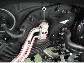
| 6. |
Disconnect the heater hoses (A)
from the heater unit.
| •
|
Engine coolant
will run out when the hoses are disconnected; drain it into
a clean drip pan. Be sure not to let coolant spill on electrical
parts or painted surfaces. If any coolant spills, rinse
it off immediately. |
|
|
| 7. |
Loosen the cowl cross member
mounting bolts.
|
| 8. |
Remove the floor console assembly.
(Refer to Body - "Floor Console Assembly")
|
| 9. |
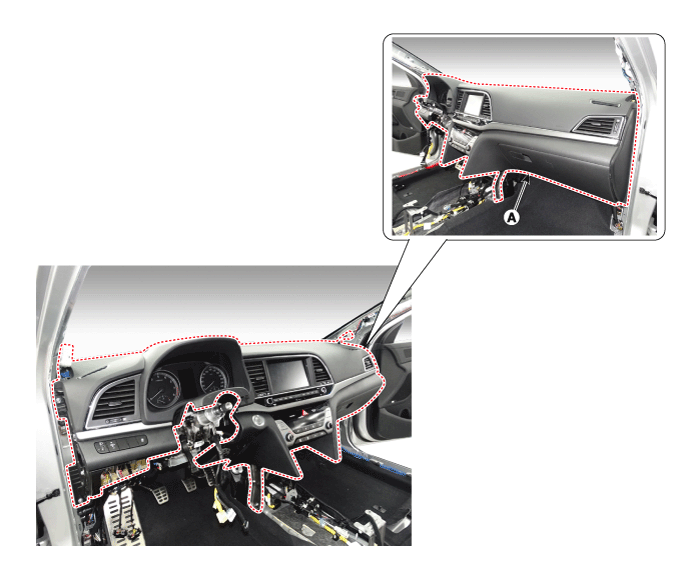
Remove the crash pad lower panel.
(Refer to Body - "Crash Pad Lower Panel")
|
| 10. |
Remove both sides of the front
pillar trim. (Refer to Body - "Front Pillar Trim")
|
| 11. |
Remove the cowl side trim.
(Refer to Body - "Cowl Side Trim")
|
| 12. |
Remove the steering column shroud
lower panel. (Refer to Body - "Steering Column Shroud Panel")
|
| 13. |
Remove the steering wheel.
(Refer to Steering System - "Steering Wheel")
|
| 14. |
Remove the multifunction switch.
(Refer to Body Electrical System - "Multifunction Switch")
|
| 15. |
Lower the steering column after
loosening the mounting bolts. (Refer to Steering System - "Steering Column
and Shaft")
|
| 16. |
Remove the shift lever assembly.
(Refer to Automatic Transmission System - "Shift Lever")
|
| 17. |
Remove the crash pad under cover
[RH](A).
|
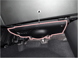
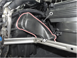
| 18. |
Remove the rear air duct (A).
|
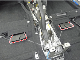
| 19. |
Separate the floor carpet (A)
to obtain space for removing the rear heating duct.
|
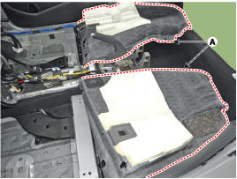
| 20. |
Loosen the mounting nuts and
remove the front air duct (A).
|
| 21. |
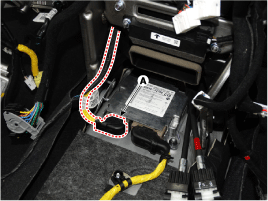
Disconnect the airbag control
module (SRSCM) connector (A).
|
| 22. |
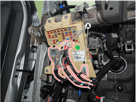
Disconnect the junction box connectors
(A).
|
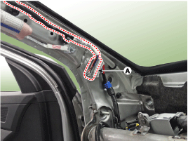
| 23. |
Disconnect the multi box connectors
(A). [Driver's side]
[Passenger's side]
|
| 24. |
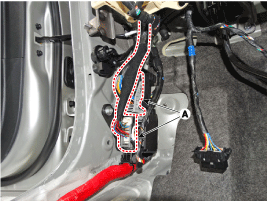
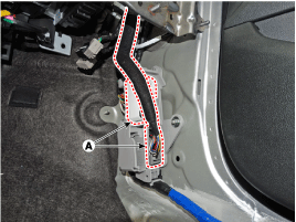
Disconnect the connectors (A)
and the mounting clips in the front pillar. [Driver's side]
[Passenger's side]
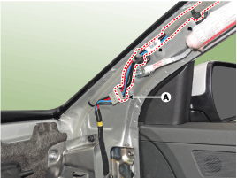
|
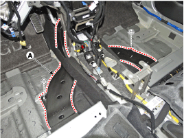
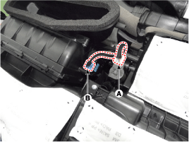
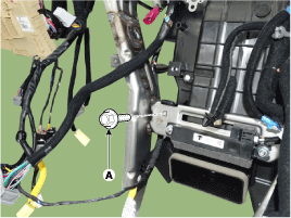
| 25. |
Remove the drain hose (A).
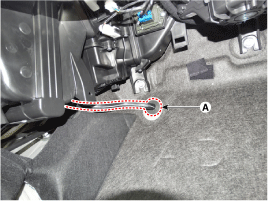
|
| 26. |
Loosen the cowl blower unit mounting
bolts.
Tightening torque :3.9
~ 5.9 N.m ( 0.4 ~ 0.6 kgf.m, 2.9 ~ 4.3 Ib-ft)
|
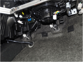
|
| 27. |
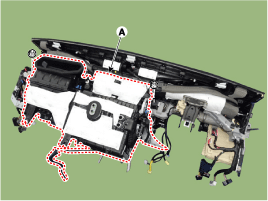
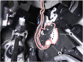
After loosening the bolts and
nuts remove the main crash pad and cowl cross bar assembly (A) together.
|
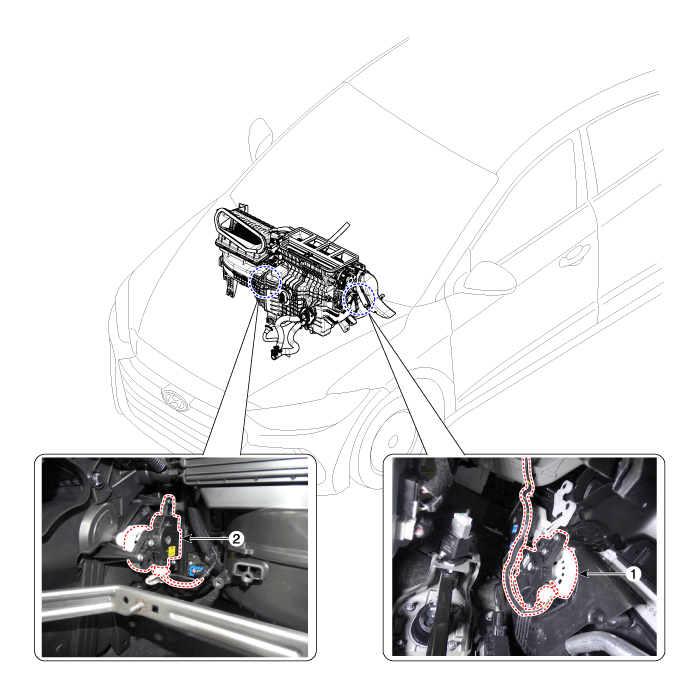
| 28. |
Disconnect the heater & blower
unit connectors.
| (1) |
Disconnect the auto defogging
actuator connector (A), intake actuator connector (B) and remove
the wiring mounting clips.
|
| (2) |
Disconnect the driver's
temperature control actuator (A), mode control actuator (B) and
remove the wiring mounting clips.

|
| (3) |
Disconnect the blower
motor connector (A) and remove the wiring mounting clips.
|
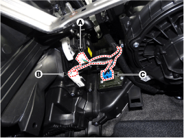
| (4) |
Disconnect the passenger's
side temperature control actuator (A), evaporator temperature sensor
connector (B), power mosfet connector (C) and remove the wiring
mounting clips.
|
|
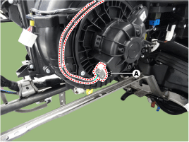
| 29. |
Loosen the heater & blower unit
mounting bolt (A).
|
| 30. |
Remove the heater and blower
unit (A) from the crash pad after loosening the mounting nuts.
Tightening torque :3.9
~ 5.9 N.m ( 0.4 ~ 0.6 kgf.m, 2.9 ~ 4.3 Ib-ft)
|
|
| 31. |
Separate the blower unit (A)
from the heater unit (B) after loosening the screws.
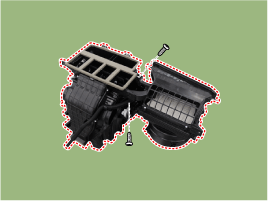
|
| 32. |
To intall, reverse the removal
procedure. |
Heater Core Repair procedures
| 1. |
Disconnect the negative (-) battery
terminal. |
| 2. |
Remove the heater and blower
assembly. (Refer to Heater - "Heater Unit")
|
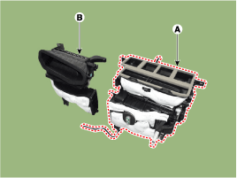
| 3. |
Remove the heater core cover
(A) after loosening the mounting screws.
|
| 4. |
Pull out the heater core (A)
from the heater unit.
|
| 5. |
To intall, reverse the removal
procedure.
| A. |
If you're installing
a new heater core, add refrigerant oil (PAG OIL). |
| B. |
Replace the O-rings with
new ones at each fitting, and apply a thin coat of refrigerant oil
before installing them. Be sure to use the right O-rings for R-134a
to avoid leakage. |
| C. |
Immediately after using
the oil, replace the cap on the container, and seal it to avoid
moisture absorption. |
| D. |
Do not spill the refrigerant
oil on the vehicle; it may damage the paint, if the refrigerant
oil contacts the paint, wash it off immediately. |
| E. |
Apply sealant to the
grommets. |
| F. |
Make sure that there
is no air leakage. |
| G. |
Charge the system and
test its performance. |
| H. |
Do not interchange the
inlet and outlet heater hoses and install the hose clamps securely.
|
|
PTC Heater Description and Operation
The PTC (Positive Temperature Coefficient) heater is installed at the exit or the
backside of heater core.
The PTC heater is an electric heater using a PTC element
as an auxiliary heating device that supplements deficiency of interior heat source
in highly effective diesel engine. The electric heater heats up the interior by
directly heating the air that passes through the heater. The name itself implies
that the element has a proportional resistance change sensitive to temperature.
Operation Principle
ECM outputs a PTC ON signal and operates PTC relay 1. Then heater controller
operates PTC relay 2 and PTC relay 3 with an interval of 15 seconds.
However, PTC relay 3 can be operated while battery voltage is above 12.4V.
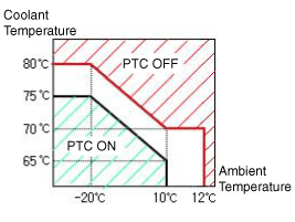
Operating
Condition
PTC heater operates according to the following conditions;
| • |
Battery voltage: 12.4V or above |
| • |
Ambient temperature and coolant
temperature |
Ambient
Temperature
|
Coolant
Temperature
|
PTC
Operation
|
Below -20°C (-4°F)
|
Below 75°C (167°F)
|
ON
|
10°C (504°F)
|
Below 65°C (149°F)
|
ON
|
12°C (53.6°F) or above
|
-
|
OFF
|
-
|
80°C (176°F) or above
|
OFF
|
PTC Heater Repair procedures
Operating Logic Test (Manual only)
Inspect the PTC operation by confirmation logic
as follows.
| 1. |
Entering
| (1) |
Set the Floor mode and
maximum heating position. |
| (2) |
Turn off the blower switch. |
| (3) |
Press the intake (recirculation)
button 5 times or more. |
| (4) |
\Indicators of intake
and A/C button are continuously flashed with an interval of 0.5
seconds. |
| (5) |
Confirm the PTC operation
by turn on the blower switch. |
| (6) |
Each PTC relay is operated
with an interval of 3 seconds. |
| (7) |
The logic test will be
automatically cancelled after 30 seconds. In addition, it can
be cancelled by followings.
| A. |
Select A/C or
intake (recirculation) switch |
|
|
| 2. |
Cancellation
| A. |
Select A/C or intake
(recirculation) switch. |
| B. |
Turn the ignition switch
OFF. |
| C. |
The test is cancelled
automatically after 30 seconds. |
|
| 3. |
If the PTC is not operated, substitute
with a known-good PTC heater and check for proper operation. If the problem
is corrected, replace the PTC heater.
|
Operating Test
This test should be performed in the PTC ON conditions.
| 2. |
Check the current on wiring with
a clamp multi tester.
Pattern
|
Current (A)
|
PTC 1 ON
|
0.1 ~ 33
|
PTC 2 ON
|
0.1 ~ 33
|
PTC 3 ON
|
0.1 ~ 33
|
Total
|
0.1 ~ 100
|
|
| 3. |
If the current is not specification,
inspect related wiring. |
Resistance Test
| 1. |
Turn the ignition switch OFF. |
| 2. |
Disconnect the PTC heater connector. |
| 3. |
Measure the resistance between
terminal 1, 2, 3 of PTC heater and ground line.
|
| 4. |
If the measured resistance is
not specification, replace the PTC heater with new one. |
| 1. |
Disconnect the negative (-) battery
terminal. |
| 2. |
Remove the floor console side
cover. (Refer to Body - "Floor Console Assembly")
|
| 3. |
Disconnect the PTC heater connector
(A).
|
| 4. |
Remove the PTC heater core (A)
after loosening the PTC heater mounting screws.
|
| 5. |
To intall, reverse the removal
procedure. |
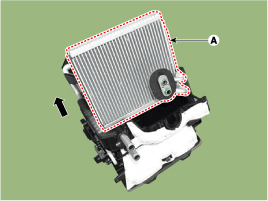
Evaporator Core Repair procedures
| 1. |
Disconnect the negative (-) battery
terminal. |
| 2. |
Remove the heater and blower
assembly. (Refer to Heater - "Heater Unit")
|
| 3. |
Remove the heater unit lower
case (A) after loosening the mounting screws.

|
| 4. |
Pull out the evaporator core
(A) from the heater unit.
|
| 5. |
To intall, reverse the removal
procedure.
| A. |
If you're installing
a new heater core, add refrigerant oil (PAG OIL). |
| B. |
Replace the O-rings with
new ones at each fitting, and apply a thin coat of refrigerant oil
before installing them. Be sure to use the right O-rings for R-134a
to avoid leakage. |
| C. |
Immediately after using
the oil, replace the cap on the container, and seal it to avoid
moisture absorption. |
| D. |
Do not spill the refrigerant
oil on the vehicle; it may damage the paint, if the refrigerant
oil contacts the paint, wash it off immediately. |
| E. |
Apply sealant to the
grommets. |
| F. |
Make sure that there
is no air leakage. |
| G. |
Charge the system and
test its performance. |
| H. |
Do not interchange the
inlet and outlet heater hoses and install the hose clamps securely.
|
|
Temperature Control Actuator Components and Components Location
1. Temperature control actuator [LH]
|
2. Temperature control actuator [RH]
|
Temperature Control Actuator Description and Operation
The temperature control actuator is located at the heater unit. It regulates the
temperature by the procedure as follows.
The signal from the control unit adjusts the position of the temperature door
by operating the temperature switch. Then the temperature will be regulated by the
hot/cold air ratio decided by the position of the temperature door.
Temperature Control Actuator Specifications
Door Position
|
Voltage (V)
|
Error Detecting
|
Max. cooling
|
0.3 ± 0.15
|
Low voltage : 0.1V or less
High voltage : 4.9V or more
|
Max. heating
|
4.7 ± 0.15
|
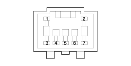
Temperature Control Actuator Repair procedures
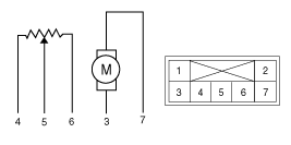
| 1. |
Turn the ignition switch OFF. |
| 2. |
Disconnect the temperature control
actuator connector. |
| 3. |
Verify that the temperature control
actuator operates to the cool position when connecting 12V to terminal 3
and grounding terminal 7. Verify that the temperature control actuator
operates to the warm position when connected in reverse.
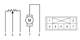
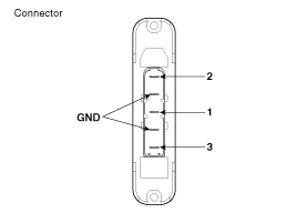
Pin NO
|
Function
|
1
|
-
|
2
|
-
|
3
|
Cool position
|
4
|
Sensor (+5V)
|
5
|
Feedback signal
|
6
|
Sensor ground
|
7
|
Warm position
|
|
| 4. |
Connect the temperature control
actuator connector. |
| 5. |
Turn the ignition switch ON. |
| 6. |
Check the voltage between terminal
5 and 6. |
| 7. |
If the measured voltage is not
within specification, check the operation by replacing the existing temperature
control actuator with a new genuine part. After that, determine whether
replacement of the temperature control actuator is required or not. |
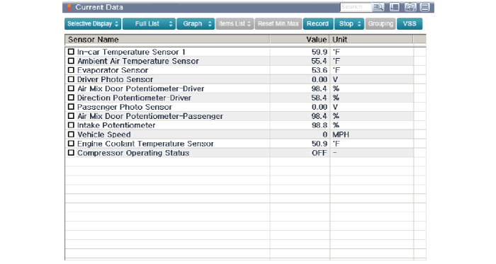
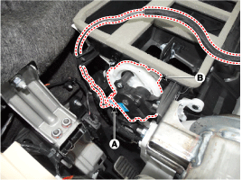
| 1. |
The heating, ventilation and
air conditioning can be quickly diagnosed failed parts with vehicle diagnostic
system (GDS).
? The diagnostic system (GDS) provides the following information. (1)
Self diagnosis : Checking the failure code (DTC) and display.
(2) Current data : Checking the system input/output data state.(3) Actuation
test : Checking the system operation condition.
(4) Additional function : Other controlling such as he system option and
zero point adjustment. |
| 2. |
Select the 'Car model' and the
system to be checked in order to check the vehicle with the tester. |
| 3. |
Select the 'Current data' menu
to search the current state of the input / output data. The input / output
data for the sensors corresponding to the Temperature Control Actuator can
be checked.
|
| 4. |
To perform compulsory operation
on Temperature Control Actuator input factors, select "ACTUATION TEST".
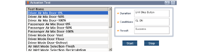
|
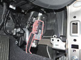
[Driver's side]
| 1. |
Disconnect the negative (-) battery
terminal. |
| 2. |
Remove the crash pad lower panel.
(Refer to Body - "Crash Pad Lower Panel")
|
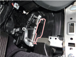
| 3. |
Remove the driver's side shower
duct (A) after loosening the screw.

|
| 4. |
Disconnect the connector (A)
and then remove the driver's side temperature control actuator (B) after
loosening the mounting screws.
|
| 5. |
To intall, reverse the removal
procedure. |
[Passenger's side]
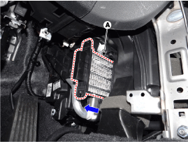
| 1. |
Disconnect the negative (-) battery
terminal. |
| 2. |
Remove the glove box upper cover
assembly. (Refer to Body - "Glove Box Upper Cover Assembly")
|
| 3. |
Remove the passenger's side shower
duct (A) after loosening the screw.
|
| 4. |
Disconnect the connector (A)
and then remove the passenger's side temperature control actuator (B) after
loosening the mounting screws.
|
| 5. |
To intall, reverse the removal
procedure. |
Mode Control Actuator Components and Components Location
Mode Control Actuator Description and Operation
The mode control actuator is located at the heater unit.
It adjusts the position
of the mode door by operating the mode control actuator based on the signal of the
A/C control unit. Pressing the mode select switch makes the mode control actuator
shift in order of Vent > Bi-Level > Floor > Mix.
Mode Control Actuator Specifications
Door position
|
Voltage (V)
|
Error detecting
|
Max. cooling
|
0.3 ± 0.15
|
Low voltage : 0.1V or less
|
Max. heating
|
4.7 ± 0.15
|
High voltage : 4.9V or more
|
Mode Control Actuator Repair procedures
| 1. |
Turn the ignition switch OFF. |
| 2. |
Disconnect the mode control actuator
connector. |
| 3. |
Verify that the mode control
actuator operates to the defrost mode when connecting 12V to terminal 3
and grounding terminal 4. Verify that the mode control actuator operates
to the vent mode when connected in reverse.
Pin NO
|
Function
|
1
|
-
|
2
|
-
|
3
|
Vent mode
|
4
|
Sensor (+5V)
|
5
|
Feedback signal
|
6
|
Sensor ground
|
7
|
Defrost mode
|
|
| 4. |
Connect the mode control actuator
connector. |
| 5. |
Turn the ignition switch ON. |
| 6. |
Check the voltage between terminal
6 and 5. |
| 7. |
If the measured voltage is not
within specification, check the operation by replacing the existing mode
control actuator with a new genuine part. After that, determine whether
replacement of the temperature control actuator is required or not. |
| 1. |
The heating, ventilation and
air conditioning can be quickly diagnosed failed parts with vehicle diagnostic
system (GDS).
? The diagnostic system (GDS) provides the following information. (1)
Self diagnosis : Checking the failure code (DTC) and display.
(2) Current data : Checking the system input/output data state.(3) Actuation
test : Checking the system operation condition.
(4) Additional function : Other controlling such as he system option and
zero point adjustment. |
| 2. |
Select the 'Car model' and the
system to be checked in order to check the vehicle with the tester. |
| 3. |
Select the 'Current data' menu
to search the current state of the input / output data. The input / output
data for the sensors corresponding to the Mode Control Actuator can be checked.
|
| 4. |
To perform compulsory operation
on Mode Control Actuator input factors, select "ACTUATION TEST".
|
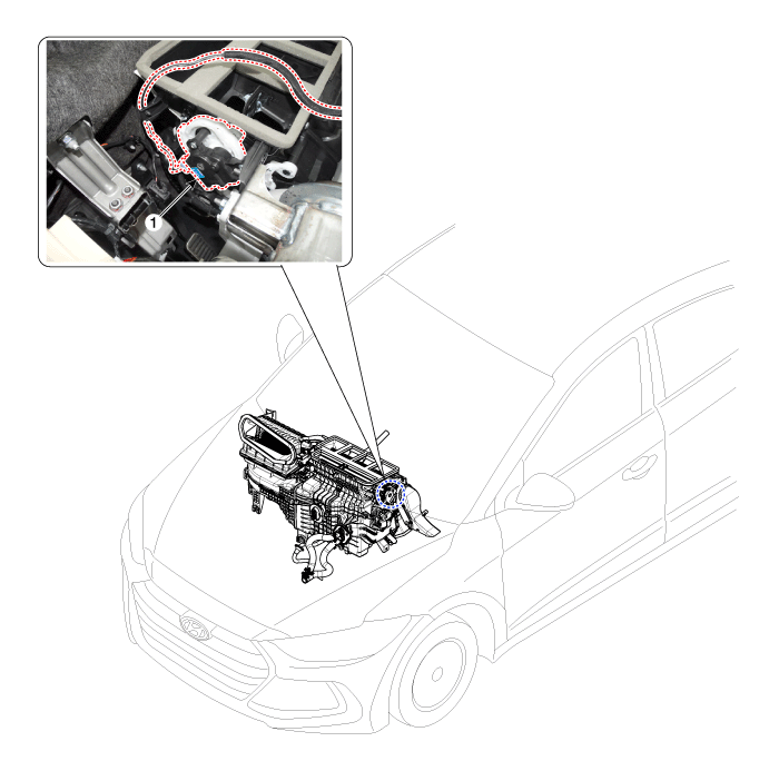
| 1. |
Disconnect the negative (-) battery
terminal. |
| 2. |
Remove the main crash pad assembly.
(Refer to Body - "Main Crash Pad Assembly")
|
| 3. |
Disconnect the connector (A)
and then remove the mode control actuator (B) after loosening the mounting
screws.
|
| 4. |
To intall, reverse the removal
procedure. |
Auto Defoging Actuator Components and Components Location
Auto Defoging Actuator Description and Operation
The auto defogging sensor is installed on front window glass. The sensor judges
and sends signal if moisture occurs to blow out wind for defogging. The air conditioner
control module receives a signal from the sensor and restrains moisture and eliminates
defog by the intake actuator, A/C, auto defogging actuator, blower motor rpm and
mode actuator.
Auto Defoging Actuator Specifications
Door position
|
Voltage (V)
|
Error detecting
|
Max. cooling
|
0.3 ± 0.15
|
Low voltage : 0.1V or less
|
Max. heating
|
4.7 ± 0.15
|
High voltage : 4.9V or more
|
Auto Defoging Actuator Repair procedures
| 1. |
Turn the ignition switch OFF.
|
| 2. |
Disconnect the auto defogging
connector. |
| 3. |
Verify that the auto defogging
actuator operates to the open position when connecting 12V to terminal 3
and grounding terminal 4.
Verify that the auto defogging actuator operates to the close position
when connected in reverse.
Pin NO
|
Function
|
1
|
-
|
2
|
-
|
3
|
Open
|
4
|
Sensor (+5V)
|
5
|
Feedback signal
|
6
|
Sensor ground
|
7
|
Off
|
|
| 4. |
Connect the auto defogging actuator
connector. |
| 5. |
Turn the ignition switch ON. |
| 6. |
Check the voltage between terminals
6 and 5. |
| 7. |
If the measured voltage is not
within specification, check the operation by replacing the existing auto
defogging actuator with a new genuine part. After that, determine whether
replacement of the auto defogging actuator is required or not. |
| 1. |
The heating, ventilation and
air conditioning can be quickly diagnosed failed parts with vehicle diagnostic
system (GDS).
? The diagnostic system (GDS) provides the following information. (1)
Self diagnosis : Checking the failure code (DTC) and display.
(2) Current data : Checking the system input/output data state.(3) Actuation
test : Checking the system operation condition.
(4) Additional function : Other controlling such as he system option and
zero point adjustment. |
| 2. |
Select the 'Car model' and the
system to be checked in order to check the vehicle with the tester. |
| 3. |
Select the 'Current data' menu
to search the current state of the input / output data. The input / output
data for the sensors corresponding to the Auto Defogging Actuator can be
checked.
|
| 4. |
To perform compulsory operation
on Auto Defogging Actuator input factors, select "ACTUATION TEST".
|
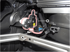
| 1. |
Disconnect the negative (-) battery
terminal. |
| 2. |
Remove the main crash pad assembly.
(Refer to Body - "Main Crash Pad Assembly")
|
| 3. |
Disconnect the connector (A)
and then remove the auto defogging actuator (B) after loosening the mounting
screws.
|
| 4. |
To install, reverse the removal
procedure. |
General Safety Information and Caution
Instructions
When Handling Refrigerant
1.
R-134a liquid refrigerant is
highly volatile. A drop on the skin of your hand could result ...
Blower Unit Components and Components Location
Component Location
1. Blower unit assembly
Components
1. Seal
2. Intake duct ca ...
 Hyundai Elantra AD: Heater


