 Hyundai Elantra CN7: Fuses And Relays
Components and components location
| Component Location |
[Engine Room]
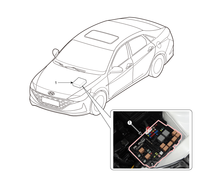
| 1. Engine room junction block |
[Interior Relay]
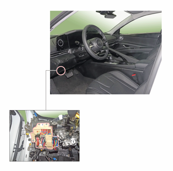
| 1. ICU (Integrated Central Control Unit) |
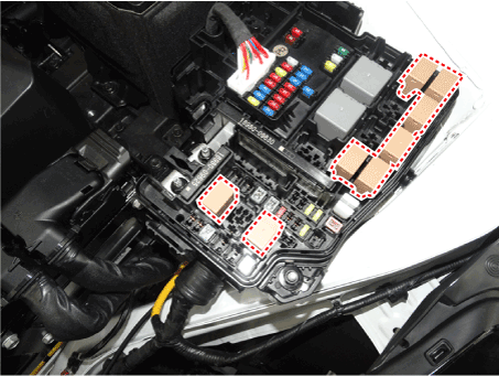
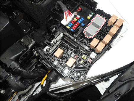
Relay Box (Engine Compartment)
Repair procedures
| Inspection |
| 1. | Disconnect the negative (-) battery terminal. |
| 2. | Pull out the relay from the engine compartment relay block. |
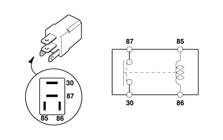
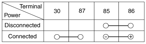
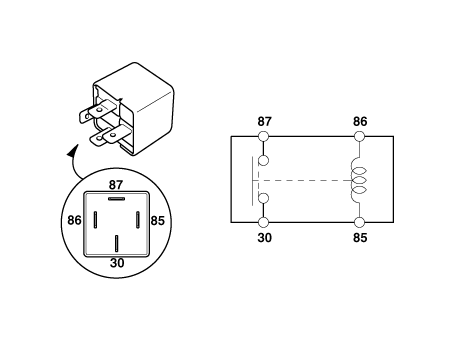
Power Relay (Type A)
Check for continuity between the terminals.
| 1. | After supplying power to between No. 85 and 86 power relay terminals, check that there is continuity between No. 30 and 87 terminals. |
| 2. | After disconnecting power between No. 85 and 86 power relay terminals, check that there is no continuity between No. 30 and 87 terminals. Engine Room Relay Block
|
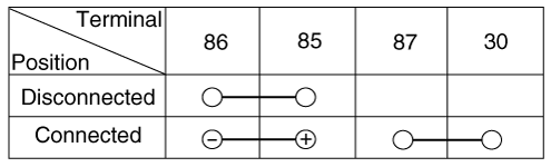
Power Relay (Type B)
Check for continuity between the terminals.
| 1. | After supplying power to between No. 85 and 86 power relay terminals, check that there is continuity between No. 30 and 87 terminals. |
| 2. | After disconnecting power between No. 85 and 86 power relay terminals, check that there is no continuity between No. 30 and 87 terminals.
|
PCB Block
| 1. | Disconnect the negative (-) battery terminal. |
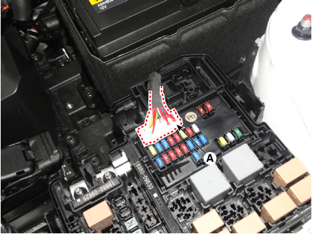
| 2. | Disconnect the PCB block connector (A).
|
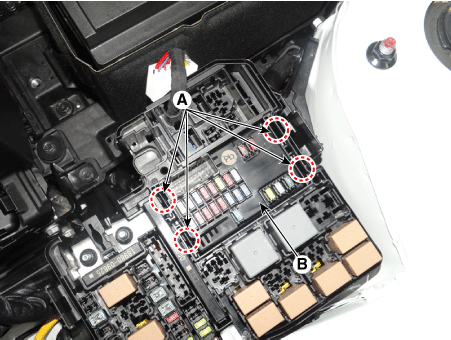
| 3. | Push the four hooks (B) in the direction of the arrow and lift up the PCB block (A).
|
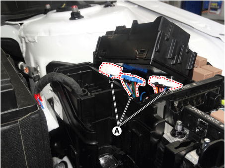
| 4. | Remove the PCB block by disconnet the connector.
|
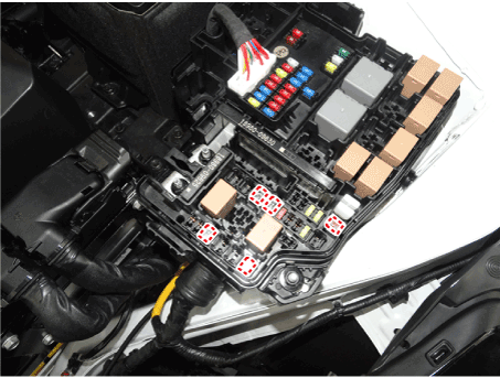
Fuse
| 1. | Check that the fuse holders are loosely held and that the fuses are securely fixed by the holders. |
| 2. | Check that each fuse circuit has the exact fuse capacity. |
| 3. | Check the fuses for any damage.
|

Multi Fuse
Engine room fuse is to optimize the package.
|

Relay Box (Passenger Compartment)
Repair procedures
| Fuse Inspection |
| 1. | Check that the fuse holders are loosely held and that the fuses are securely fixed by the holders. |
| 2. | Check that each fuse circuit has the exact fuse capacity. |
| 3. | Check the fuses for any damage.
|
Diagnosis with Diagnostic tool
| 1. | In the body electrical system, failure can be quickly diagnosed by using the vehicle diagnostic system (Diagnostic tool). The diagnostic system(Diagnostic tool) provides the following information.
|
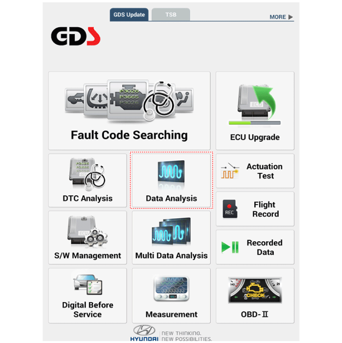
| 2. | If diagnose the vehicle by Diagnostic tool, select "DTC Analysis" and "Vehicle".
|

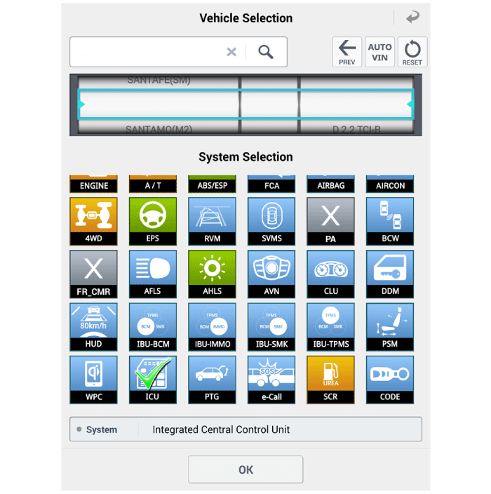
| 3. | If check current status, select the "Data Analysis" and "Car model".
|
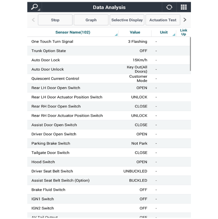
| 4. | Select the 'ICU' to search the current state of the input/output data.
|
| Removal |
| 1. | Disconnect the negative (-) battery terminal. |
| 2. | Remove the crash pad lower panel. (Refer to Body - "Crash Pad Lower Panel") |
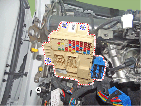
| 3. | Disconnect the connectors from the fuse side of the ICU.
|
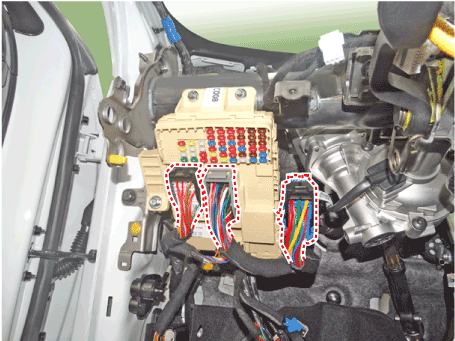
| 4. | Remove the ICU (A) after loosening the mounting nuts.
|
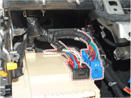
| 5. | Disconnect the connectors from the back side of the ICU.
|
| Installation |
| 1. | Install the smart junction box. |
| 2. | Install the crash pad lower panel. |
| 3. | Connect the negative (-) battery terminal. |
| 4. | Check that all system operates normally. |

