Description and operation
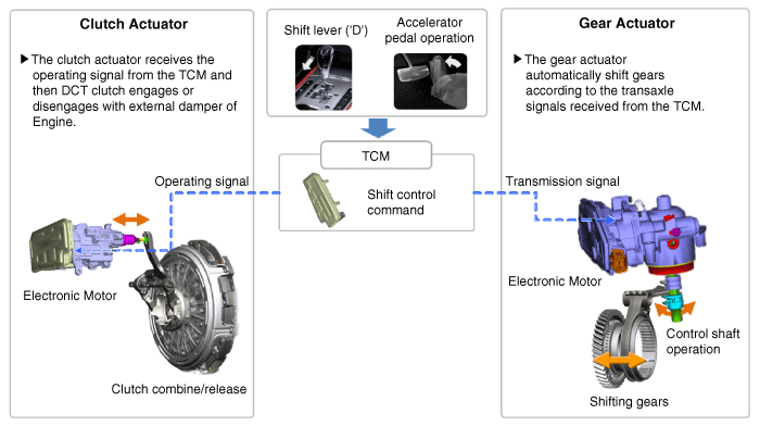
The Dual Clutch Transmission (DCT) control system measures required data to identify the state of the control target and computes the appropriate compensation value if adjustment is necessary. The actuator is controlled according to the computed compensation value to obtain desired output.
If transmission or driving-performance-related failure is detected, first perform self-diagnosis and basic transmission inspection (oil check).
Then use the diagnostic tool to inspect the transmission control system components.
DCT Control Module (TCM)
Description and operation
| •
|
Function
The Transmission Control Module (TCM) is like the brain for the Dual Clutch Transmission (DCT). It receives information from various sensors for a wide range of transmission controls to provide an optimal driving environment for the driver. The TCM is programmed for optimal operation in all driving conditions. If the TCM malfunctions, store the failure information in memory and provide the error information to a mechanic for fast and accurate repair. |
Components and components location
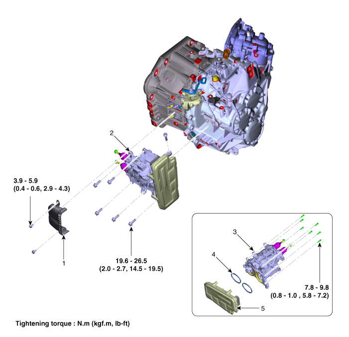
1. Fork cover
2. Clutch actuator & TCM assembly
3. Clutch actuator assembly
| 4. O-ring
5. DCT control module (TCM)
|
Schematic diagrams
| Connector and Terminal Function |
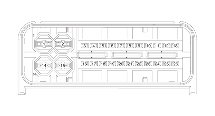
Pin
|
Description
|
Pin
|
Description
|
1
| Ground 2 (Power)
| 14
| Battery power 2 (Motor)
|
2
| Ground 1 (Power)
| 15
| Battery power 1 (Motor)
|
3
| Shift lock solenoid
| 16
| Battery voltage (Low Power)
|
4
| Paddle shift "Up"
| 17
| P-CAN 1 Low
|
5
| Paddle shift "Down"
| 18
| P-CAN 1 High
|
6
| Inhibitor switch signal "R"
| 19
| Local-DCT 1 Low
|
7
| Inhibitor switch signal "N"
| 20
| Local-DCT 1 High
|
8
| Inhibitor switch signal "D"
| 21
| Local-DCT 2 Low
|
9
| Inhibitor switch signal "P"
| 22
| Local-DCT 2 High
|
10
| -
| 23
| PT-Local 1 Low
|
11
| Ignition voltage
| 24
| PT-Local 1 High
|
12
| Input speed sensor signal 2 (Even)
| 25
| Input speed sensor signal 1 (Odd)
|
13
| Input speed sensor power 2 (9 V)
| 26
| Input speed sensor power 1 (9 V)
|
Repair procedures
| Transmission Control Module (TCM) Inspection Procedure |
| 1. | Inspecting TCM ground circuit: Measure the resistance between the TCM and chassis ground. (Check the terminal connected to the chassis ground while using the back of the harness connector as the base point for TCM.) Normal reading (resistance): Below 1Ω |
|
| 2. | Inspecting the TCM connector: Disconnect the TCM connector and visually inspect to see whether there is a bend on the ground terminal of the harness connector. Also visually check the connection pressure. |
| 3. | If no problem is found during inspection in step 1 and step 2, then the problem is with the TCM itself. In this case, replace the TCM and inspect the vehicle again. |
| 4. | Re-inspecting TCM: Install the TCM that was determined to have malfunctioned from step 3 in another vehicle. Reset the error code and then check the operation in that vehicle. If the vehicle operates without any problems, then inspect the first vehicle with the initial problem again. |
| 1. | Prior to replacing the TCM, check the TCM clutch compensation value with the diagnostic tool tool. 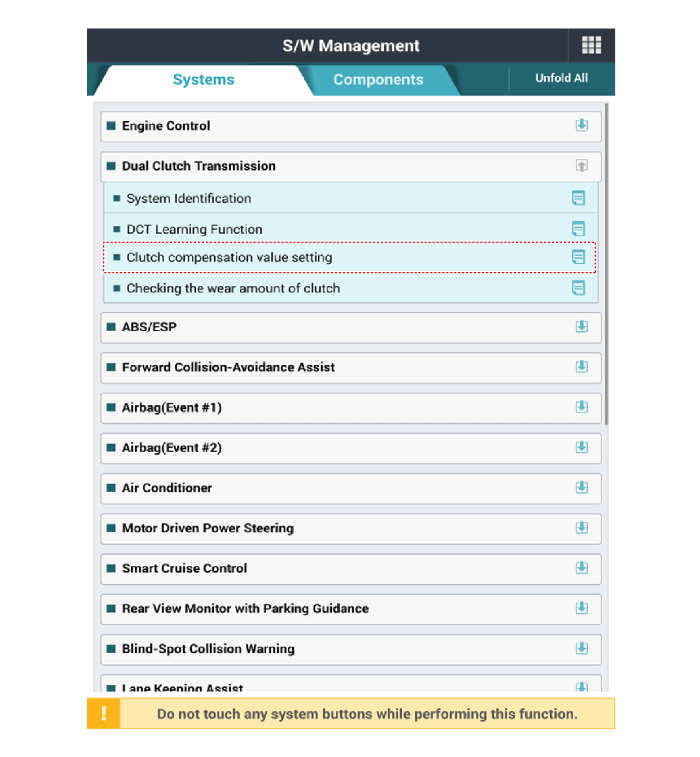
|
| 2. | Turn ignition switch OFF and disconnect the battery negative (-) terminal. |
| 3. | Remove the clutch actuator assembly. (Refer to Dual Clutch Transmission Control System - "Clutch Actuator Assembly") |
| 4. | Loosen the bolts (A) and then removing the TCM (B). Tightenning torque: 9.8 - 11.8 N.m (1.0 - 1.2 kgf.m, 7.2 - 8.7 lb.ft) |
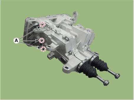
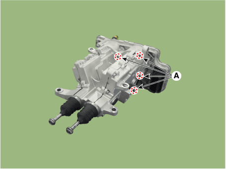
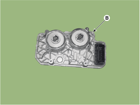
|
| 1. | To install, reverse the removal procedure. | •
| The existing O-rings (A) must be replaced with a new one. (Do not reuse it.) 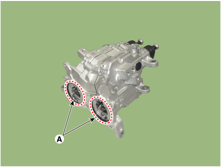
|
|
|
| 2. | Perform the clutch compensation value setting procedure using the diagnostic tool after replacing TCM. 
|
| 3. | Perform the clutch touch point learning procedure using the diagnostic tool after replacing TCM 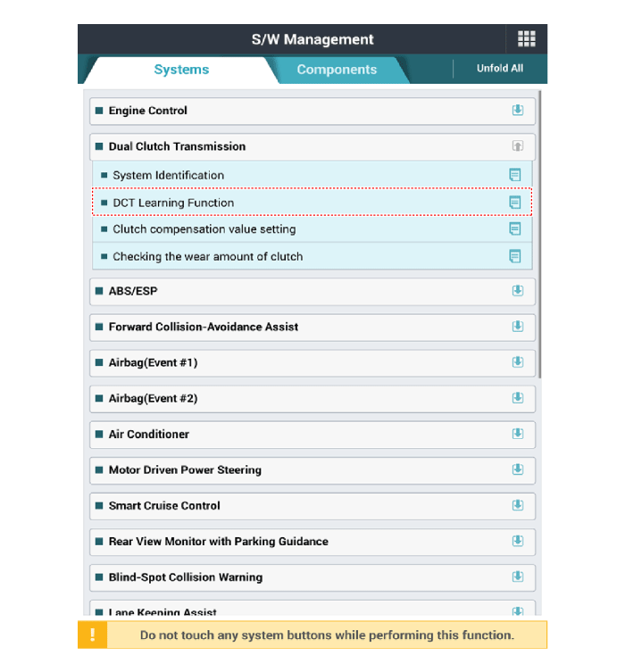
|
Clutch Actuator & TCM Assembly
Specifications
Item
|
Specification
|
Rated voltage
| 12V
|
Rod length
| 79.0 - 80.0 mm (3.1102 - 3.1496 in.)
|
Wear adjustment amount
| 0.25 mm (0.0098 in.) @ 1 Click
|
Components and components location

1. Fork cover
2. Clutch actuator & TCM assembly
3. Clutch actuator assembly
| 4. O-ring
5. DCT control module (TCM)
|
Repair procedures
| 1. | The DCT system can be more quickly diagnosed for troubles by using the vehicle diagnostic system (diagnostic tool). (Refer to DTC guide) diagnostic tool provides the following information. | 1) | Self diagnosis : Inspects and displays diagnostic trouble code (DTC) |
| 2) | Sensor data : Checks the system input/output value status |
| 3) | Forced operation : Checks the system operating status |
| 4) | Additional function : Controls system options, zero point adjustment and other functions |
|
| 1. | Turn ignition switch OFF and disconnect the battery negative (-) terminal. |
| 2. | Remove the air cleaner assembly. (Refer to Engine Mechanical System - "Air cleaner") |
| 3. | Disconnecting the TCM connector (A). |
| 4. | Loosen the bolts and then remove the ground line (A). 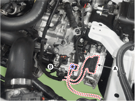
|
| 5. | Loosen the bolts and then remove the ground line (A). 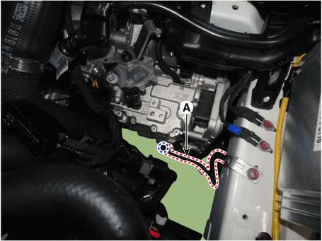
|
| 6. | Loosen the clutch actuator upper mounting bolts (A). Tightening torque : 19.6 - 26.5 N.m (2.0 - 2.7kgf.m, 14.5 - 19.5 lb-ft) |
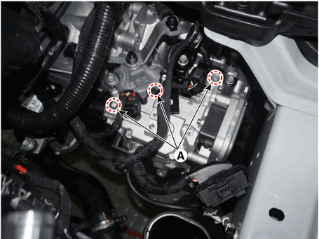
|
| 7. | Remove the engine room under cover. (Refer to Engine Mechanical System - "Engine Room Under Cover") |
| 8. | Loosen the starter lower mounting bolt (A) and transmission lower mounting bolt (B). Tightening torque : (A) : 49.0 - 63.7 N.m (5.0 - 6.5 kgf.m, 36.2 - 47.0 lb-ft) (B) : 42.2 - 53.9 N.m (4.3 - 5.5 kgf.m, 31.1 - 39.8 lb-ft) |
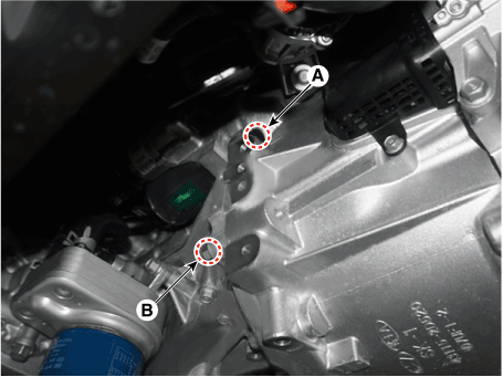
|
| 9. | Loosen the bolt and then remove the fork cover (A) and wiring bracket (B). Tightening torque : (A) : 3.9 - 5.9 N.m (0.4 - 0.6 kgf.m, 2.9 - 4.3 lb-ft) (B) : 9.8 - 11.8 N.m (1.0 - 1.2 kgf.m, 7.2 - 8.7 lb-ft) |
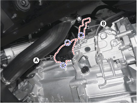
|
| 10. | Fix the clutch engagement fork after installing special service tool (0K430-Q5100). 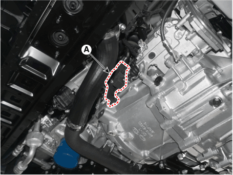
| •
| Rotating a bolt after installing special service tool (0K430-Q5100) (A). 
|
|
|
| 11. | Remove the clutch actuator & TCM assembly (A) after loosening the lower mounting bolts. Tightening torque : 19.6 - 26.5 N.m (2.0 - 2.7kgf.m, 14.5 - 19.5 lb-ft) |
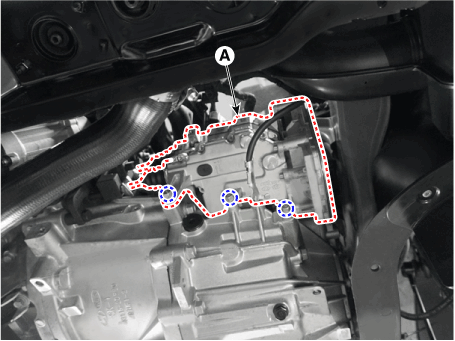
|
| 12. | If you have replaced the dual clutch assembly or clutch actuator, perform wear compensation on the clutch actuator. (Refer to Clutch Actuator Assembly - "Adjustment") |
| 1. | To install, reverse the removal procedures. |
| 2. | Check the assembled state of the dowel pins (A) before installing the clutch actuator assembly. 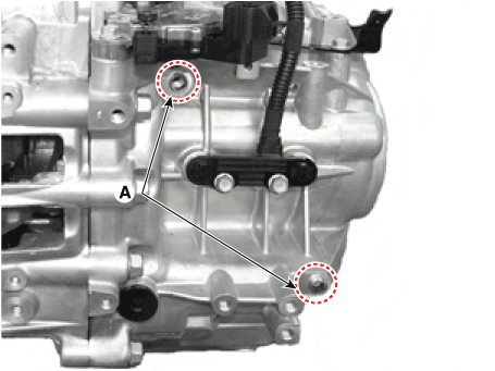
|
| 3. | Perform the clutch touch point learning procedure using the diagnostic tool. 
| •
| Even if you removed and reinstalled the clutch actuator, be sure to perform the touch point learning. |
| •
| If you have replaced the dual clutch assembly or clutch actuator, be sure to perform the touch point learning. |
|
|
| •
| If you replaced the dual clutch assembly or clutch actuator, be sure to perform wear compensation by referring to the following table.
Case
| Replaced Part
| Wear Compensation (Clutch Actuator)
| A
| Clutch actuator only
| Rewind the rod to adjust rod length
| B
| Dual Clutch assembly only
| Initialize the rod length
| C
| Both dual clutch assembly and clutch actuator
| Do not adjust the rod length
|
|
|
A. Rewinding the rod to adjust rod length (when only the clutch actuator is replaced)
| •
| Be sure to perform it when you have replaced the clutch actuator but reuse the dual clutch assembly. |
| •
| It is performed to adjust the rod length of a new clutch actuator to that of an old clutch actuator. |
|
| 1. | Remove the clutch actuator assembly. (Refer to Clutch Actuator Assembly - "Removal") |
| 2. | Slightly pull the lever of the clutch actuator removed from the vehicle and measure the length of each old rod (C). Length of the old rod (C) : Length from the reference plane (A) to the end of the rod (B). |
| 2) | Clutch actuator 2 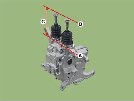
|
| •
| If the rod length is less than 52 mm (2.0472 in.), replace all of the dual clutch assembly, clutch actuator, and engagement bearing. |
|
|
| 3. | Remove sealing rubber (A) of new part clutch actuator. 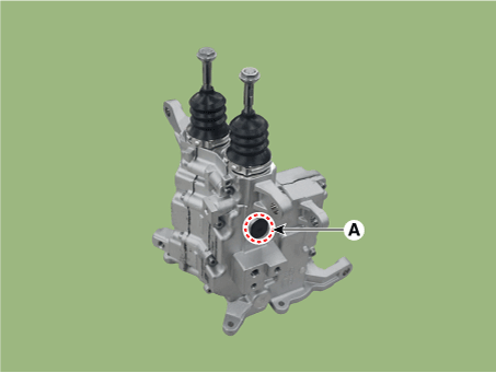
|
| 4. | Press the end part of rod (A) and release the pressing force when you see the nut bump (B). 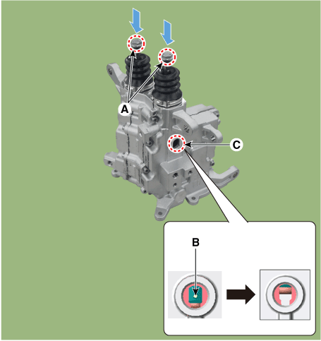
| •
| Light inside of the hole (C) and check the nut bump (B) inside of it. |
| •
| Repeat the operation if the nut bump (B) does not come down to the assembly hole position. |
| •
| The nut bump (B) can be moved up a little by sealing boot if the pressing force is released. |
|
|
| 5. | Insert a special tool (0K430-Q5300) (A) to a sealing rubber hole. Rotate the SST clockwise and adjust the length of the new clutch actuator's rod to the "length of old rod", which was measured at step No. 2. Increasing (+) rod length : Rotate counter-clockwise / once +0.25mm (+0.0098 in.) Shortening (-) rod length : Rotate clockwise / once -0.25mm (-0.0098 in.) |
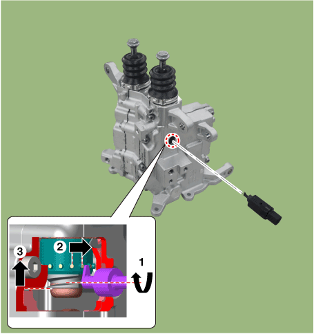
| •
| Perform the same procedure for the opposite side rod. |
|
| •
| Be aware not to break the clutch actuator caused by break away inner parts when the SST over rotates clockwise. |
| •
| If the "length of the clutch actuator's new rod" is not adjusted to the "length of the old rod" measured at step No. 2, the DCT shift shock may occur or driving may be impossible. |
|
|
| 6. | Slightly pull the lever of the clutch actuator and check whether the "length of the rod which the final adjustment is finished" is same with the "length of the old rod" measured at step No. 2. Rod length (C) : Length from the reference plane (A) to the end of the rod (B). |

|
| 7. | Install the sealing rubber (A). 
|
B. Initializing the rod length (When only the dual clutch assembly is replaced or Both dual clutch assembly and clutch actuator is replaced)
| •
| Be sure to perform it when you have replaced the dual clutch assembly but reuse the clutch actuator. |
| •
| Perform the procedure when both the dual clutch assembly and clutch actuator are replaced. |
| •
| It is performed to adjust the rod length of an old clutch actuator to that of a new clutch actuator. |
|
| 1. | Remove the clutch actuator assembly. (Refer to Clutch Actuator Assembly - "Removal") |
| 2. | Remove sealing rubber (A) from old part clutch actuator. 
|
| 3. | Slightly pull the lever of the clutch actuator removed from the vehicle and measure length of each rod (C). If the length is shorter than the initialization length, you need to perform initialization. Rod length (C) : Length from the reference plane (A) to the end of the rod (B). (Initializ rod length : 79.0 - 80.0 mm (3.1102 - 3.1496 in.) |
| 2) | Clutch actuator 2 
|
|
| 4. | Press the end part of rod (A) and release the pressing force when you see the nut bump (B). 
| •
| Light inside of the hole (C) and check the nut bump (B) inside of it. |
| •
| Repeat the operation if the nut bump (B) does not come down to the assembly hole position. |
| •
| The nut bump (B) can be moved up a little by sealing boot if the pressing force is released. |
|
|
| 5. | Insert a special tool (0K430-Q5300) (A) to a sealing rubber hole. Rotate the SST counter-clockwise and adjust the length of the clutch actuator's rod. Increasing (+) rod length : Rotate counter-clockwise / once +0.25mm (+0.0098 in.) Shortening (-) rod length : Rotate clockwise / once -0.25mm (-0.0098 in.) |
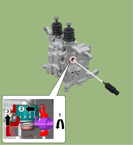
| •
| Perform the same procedure for the opposite side rod. |
|
| •
| Be aware not to break the clutch actuator caused by break away inner parts when the SST over rotates clockwise. |
| •
| If the rod length is not initialized to 79.0 - 80.0 mm (3.1102 - 3.1496 in.) during initialization of wear compensation, DCT shift shock may occur or driving may be impossible. |
|
|
| 6. | Slightly pull the lever of the clutch actuator and check whether the "length of the rod which the final adjustment is finished" is same with the "rod's initialized length". Rod length (C) : Length from the reference plane (A) to the end of the rod (B). (Initializ rod length : 79.0 - 80.0 mm (3.1102 - 3.1496 in.) |
| 2) | Clutch actuator 2 
|
|
| 7. | Install the sealing rubber (A). 
|
| 8. | Remove the clutch actuator assembly from the special tool (0K430-Q5300). |
Gear Actuator Assembly
Description and operation
| •
| Gear actuator uses signals from TCM to control the gear. |
Specifications
Item
|
Specification
|
Operation condition
| -40 to 257 °F (- 40 to 125 °C )
|
Rated voltage
| 12V
|
Components and components location
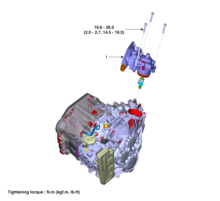
1. Gear actuator assembly
|
|
Schematic diagrams
| [Connector and Terminal Function] |
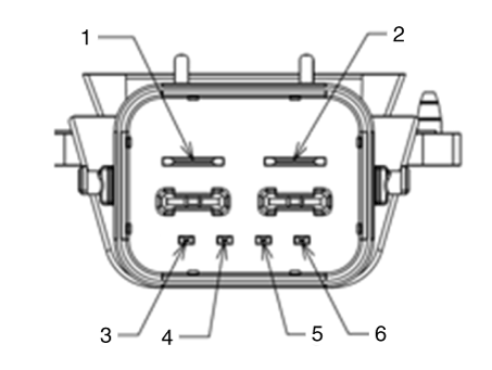
Pin
|
Description
|
Pin
|
Description
|
1
| Ground (Power)
| 4
| CAN3 Low
|
2
| Battery Power
| 5
| CAN4 High
|
3
| CAN3 High
| 6
| CAN4 Low
|
Repair procedures
| 1. | The DCT system can be more quickly diagnosed for troubles by using the vehicle diagnostic system (diagnostic tool). (Refer to DTC guide) diagnostic tool provides the following information. | 1) | Self diagnosis : Inspects and displays diagnostic trouble code (DTC) |
| 2) | CAN signals : Checks the system input/output value status |
| 3) | Forced operation : Checks the system operating status |
| 4) | Additional function : Controls system options, zero point adjustment and other functions |
|
| 1. | Turn ignition switch OFF and disconnect the battery negative (-) terminal. |
| 2. | Remove the air cleaner assembly and air duct. (Refer to Engine Mechnical System - "Air Cleaner") |
| 3. | Remove the battery and battery tray. (Refer to Engine Electrical System - "Battery") |
| 4. | Loosen the bolts and then remove the ground line (A). 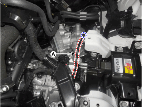
|
| 5. | Disconnect the gear actuator connector (A). 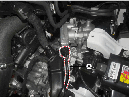
|
| 6. | Remove the gear actuator assembly after loosening bolts (A). Tightening torque : 19.6 - 26.5 N.m (2.0 - 2.7 kgf.m, 14.5 - 19.5 lb-ft) |
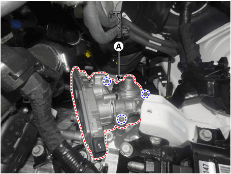
|
| 1. | To install, reverse the removal procedure. | •
| Check the details below before installing the gear actuator assembly. |
| 1) | Check that the gear actuator is placed in the "neutral" state. |
| 2) | Check the assembled state of the O-rings (A). 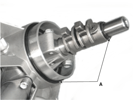
|
| 3) | Apply gear oil to the surface of O- rings. |
| 4) | Check the assembled state of the dowel pins (A). 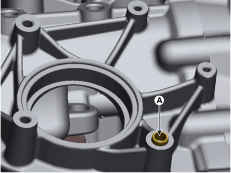
|
| •
| Perform the clutch touch point learning procedure using the diagnostic tool after replacing the clutch actuator assembly. 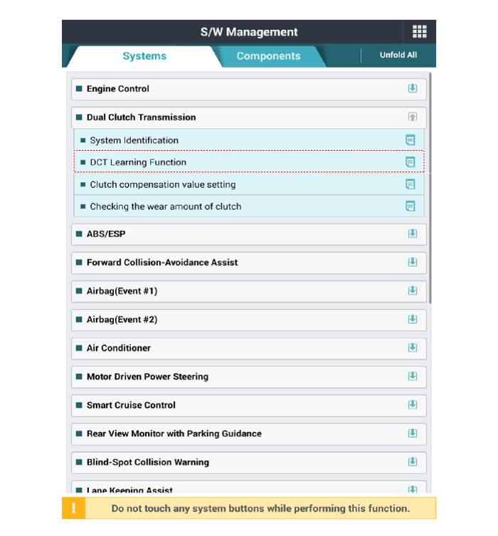
|
|
|
Input Speed Sensor
Description and operation
| •
|
Components location : DCT (Dual Clutch Transmission) 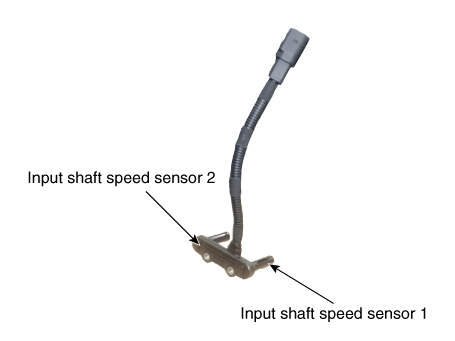
|
| •
|
Function
The input shaft speed sensor is important in that it detects the input shaft RPM and sends this information to the Transmission Control Module (TCM). It provides important input information for electric control. The information is needed in all operations, including feedback control, gear shift control and failure detection of other sensors. |
Specifications
Item
|
Specification
|
Type
| Hall effect sensor
|
Output signal
| High: 11.8 - 16.8 mA
|
Low: 5.9 - 8.4 mA
|
Schematic diagrams
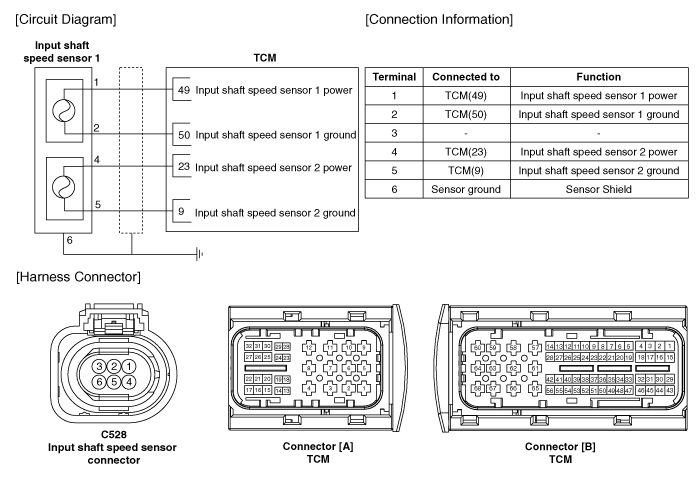
Components and components location
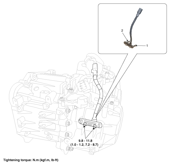
1. Input shaft speed sensor 1 (Odd)
| 2. Input shaft speed sensor 2 (Even)
|
Repair procedures
| 1. | The DCT system can be more quickly diagnosed for troubles by using the vehicle diagnostic system (diagnostic tool). (Refer to DTC guide) diagnostic tool provides the following information. | 1) | Self diagnosis : Inspects and displays diagnostic trouble code (DTC) |
| 2) | Sensor data : Checks the system input/output value status |
| 3) | Forced operation : Checks the system operating status |
| 4) | Additional function : Controls system options, zero point adjustment and other functions |
|
| 1. | Turn ignition switch OFF and disconnect the battery negative (-) terminal. |
| 2. | Remove the air cleaner assembly and air duct. (Refer to Engine Mechnical System - "Air cleaner") |
| 3. | Disconnect the input shaft speed sensor connector (A). 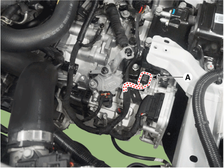
|
| 4. | Remove the clutch actuator. (Refer to Dual Clutch Transmission Control System - "Clutch Actuator & TCM Assembly") |
| 5. | Remove the input shaft speed sensor (A). Tightening torque : 9.8 - 11.8 N.m (1.0 - 1.2kgf.m, 7.2 - 8.7 lb-ft) |
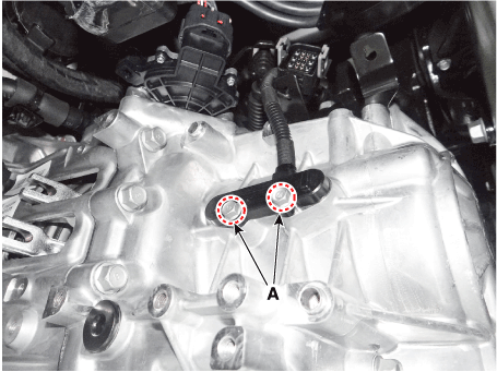

|
| 1. | Install in the reverse order of removal. | •
| Before installing the input speed sensor,check the assembled state of the O-rings (A) and should apply gear oil to the surface of O- rings. 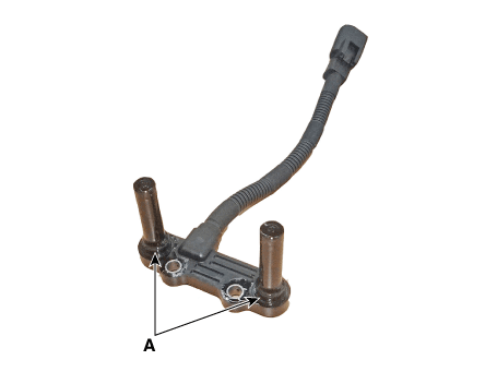
|
|
|
Inhibitor Switch
Description and operation
| •
| The inhibitor switch is installed on top of transmission, and is connected to the shift lever through shift cable. |
| •
| Inhibitor switch signals (S1, S2, S3, S4) are transmitted to the TCM according to the driver's shift lever control. 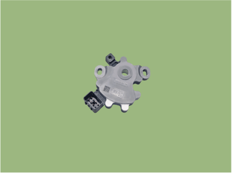
|
Specifications
Item
|
Specification
|
Power supply
| 12V
|
Output type
| Combination of output signals
|
|
P
|
Pst (P - R)
|
R
|
Nst (R - N)
|
N
|
N-D
|
D
|
Signal "1"
| 12V
| 12V
| 0
| 0
| 0
| 0
| 0
|
Signal "2"
| 0
| 12V
| 12V
| 12V
| 0
| 0
| 0
|
Signal "3"
| 0
| 0
| 0
| 12V
| 12V
| 12V
| 0
|
Signal "4"
| 0
| 0
| 0
| 0
| 0
| 12V
| 12V
|
Components and components location
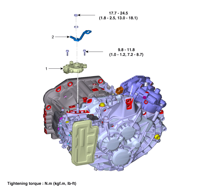
1. Inhibitor switch
| 2. Manual control lever
|
Troubleshooting
| Fault Diagnosis for Symptom |
Major Symptom
|
Expected Cause
|
Items to Check and Measures
|
Shift lever not operating
Gear not marked on cluster
Shock occurs while shifting lever Warning lamp ON
Engine OFF while vehicle is parked
| Inhibitor switch circuit abnormal
Inhibitor switch function abnormal
| Check the inspection FLOW and replace the inhibitor switch
|
Inhibitor switch "N" setting faulty
| Adjust "N" setting using "N" setting jig (refer to automatic transmission system - "inhibitor switch")
|
Shift cable separation faulty
| Adjust shift cable separation (refer to automatic transmission system - "inhibitor switch")
|
Poor ground condition on reversing light circuit
| Check the ground condition on reversing light and retighten it
|
Inhibitor switch vehicle side circuit abnormal
| Check the connection of junction box power terminal, fuse (TCU2) terminal and replace the junction box or adjust the gap
|
Check inside the inhibitor switch connector for foreign substance and whether terminal is bent
|
Poor ground condition on inhibitor switch wire
| Check the ground condition of wire and retighten it
|
Poor inhibitor unit (disconnection/short-circuit)
| Replace inhibitor switch (refer to inhibitor switch inspection)
|
Repair procedures
| •
| Thoroughly check connectors for looseness, poor connection, bending, corrosion, contamination, deterioration, or damage. |
|
Inspection flow
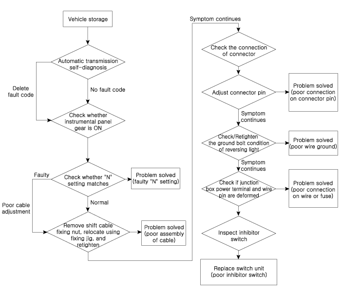
Items to check
| 2. | Inspect whether N setting matches. | –
| Adjust N setting (refer to automatic transmission system - "inhibitor switch") |
|
| 3. | Inspect shift cable separation. | –
| Adjust shift cable separation (refer to automatic transmission system - "shift cable") |
|
| 4. | Inspect whether connector is connected. | –
| Inspect connector thoroughly for looseness, poor connection, bending, corrosion, contamination, deformation, or damage. |
| –
| Turn ignition key "ON" and engine "OFF" and measure the power supplied to inhibitor switch circuit and voltage between ground. Specification : approx. 12 V |
|
| –
| Fix the pin wiring when connector pin wiring is faulty (refer to ETM - "wiring repair"). |
|
| 5. | Inspect ground condition on reversing light circuit. | –
| Check the ground location of reversing light (refer to ETM - "harness location map"). |
| –
| Reattach reversing light if ground condition is faulty. |
|
| 6. | Inspect wiring connection on junction box power terminal and fuse lamp. | –
| Check whether fuse holder is separated and holder is holding the fuse tight. 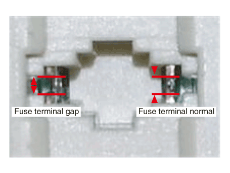
|
| –
| Attach tester fuse to check if it is connected appropriately. 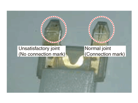
|
| –
| Check whether fuse capacity is appropriate for each circuit. |
| –
| Check if fuse is damaged. |
| –
| Check pulling of fuse fixing wiring, inflow of foreign substance, and arrangement condition of terminal. |
| –
| Relocate the terminal that has been pulled and inspect using the method explained above. |
| –
| When problem is not solved, refer to the circuit diagram wiring repair instructions to fix or replace the terminal. |
|
| 7. | Inspect inhibitor switch signal. | –
| Turn ignition key "ON" and engine "OFF". |
| –
| Measure the voltage between each terminal and chassis ground when shifting lever to "P, R, N, D" range. Specified value: refer to specification "signal code" table |
|
|
| 1. | Make sure vehicle does not roll before setting shift lever to "N" position. |
| 2. | Turn ignition switch OFF and disconnect the battery negative (-) terminal. |
| 3. | Remove the air cleaner assembly and air duct. (Refer to Engine Mechnical System - "Air cleaner") |
| 4. | Disconnect the inhibitor switch connector (B). 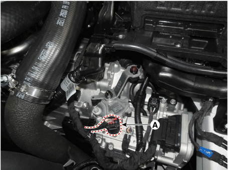
|
| 5. | Loosen the shift cable mounting nut (A). 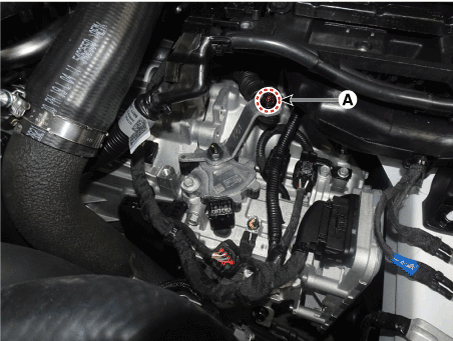
|
| 6. | Loosen the manual lever mounting nut (A) and inhibitor swtich mounting bolts (B) and then remove the inhibitor switch (C). 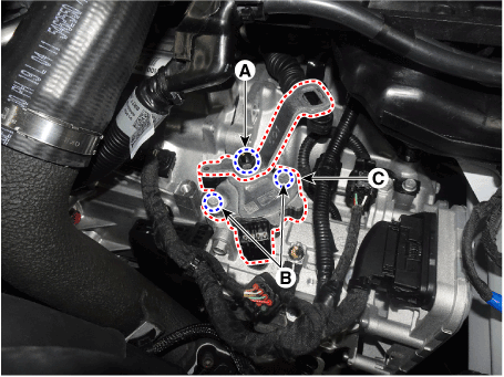
|
| 1. | Check that the shift lever is placed in the "N" position. |
| 2. | Lightly tighten the inhibitor switch mounting bolts after installing the inhibitor switch (A). 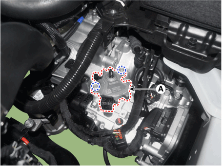
|
| 3. | Lightly tighten the manual control lever mounting nut (B) after installing the manual control lever (A). 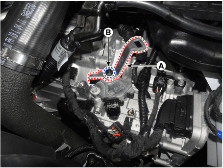
|
| 4. | Align the hole in the manual control lever with the "N" position hole of the inhibitor switch and then insert the inhibitor switch guide pin (SST No. : 09480 - A3800) (A) in the matched hole. 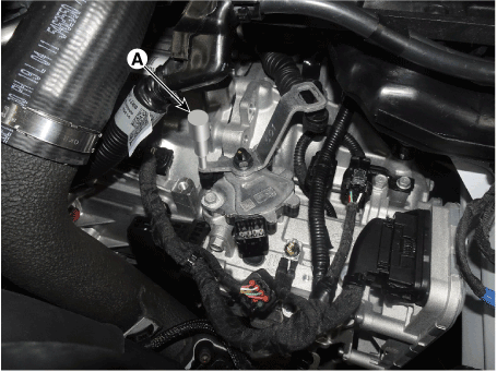
|
| 5. | Tighten the nut (A), bolts (B) with the specified torque. Tightening torque : (A) 17.7 - 24.5 N.m (1.8 - 2.5 kgf.m, 13.0 - 18.1 lb-ft) (B) 9.8 - 11.8 N.m (1.0 - 1.2 kgf.m, 7.2 - 8.7 lb-ft) |
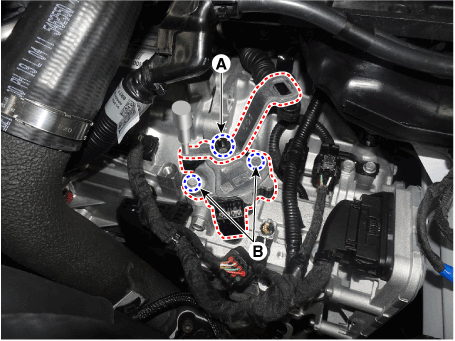
|
| 6. | Lightly tighten the nut (A) after connected the shift cable in the manual control lever. |
| 7. | Push shift cable lightly to "F" direction shown to eliminate free play of shift cable. |
| 8. | Tighten the nut (A) with the specified torque. Tightening torque : 9.8 - 13.7 N.m (1.0 - 1.4 kgf.m, 7.2 - 10.1 lb-ft) |
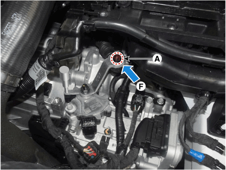
|
| 9. | Connect the inhibitor switch connector (A). 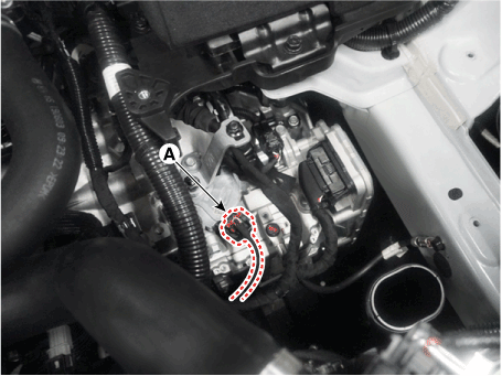
|
| 10. | Remove the inhibitor switch guide pin (SST No. : 09480-A3800) from the hole. 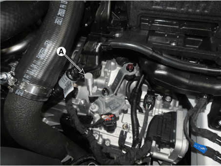
|
| 11. | Install the air cleaner and air duct. (Refer to Engine Mechanical System - "Air Cleaner") | •
| Check that operating surely at each range of the inhibitor switch corresponding to each position of shift lever. |
|
|
Shift Lever
Components and components location
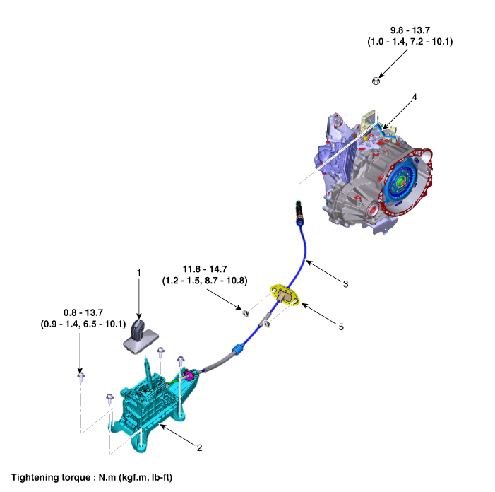
1. Shift lever knob & boots assembly
2. Shift lever assembly
3. Shift cable
| 4. Manual control lever
5. Shift cable retainer
|
Repair procedures
| 1. | Turn OFF ignition switch and then diconnect the battery negative (-) cable. |
| 2. | Remove the shift lever knob & boots (A). 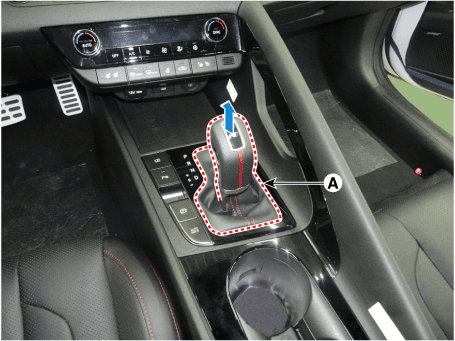
|
| 3. | Remove the floor console assembly. (Refer to Body - "Floor Console") |
| 4. | Remove the air duct (A) after loosening the bolts. 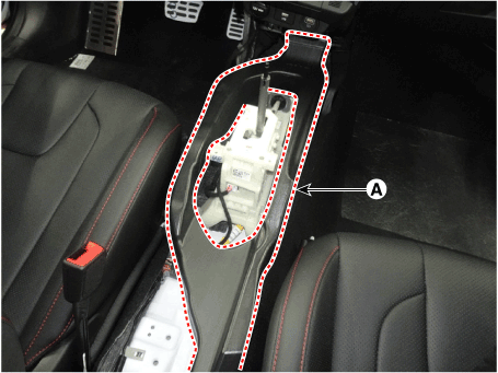
|
| 5. | Separate the shift cable (B) after removing the snap pin (A). 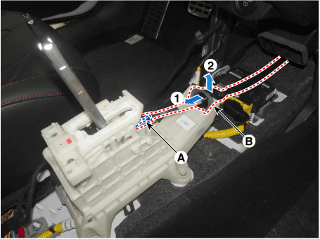
|
| 6. | Disconnect the connector (A) and wiring clip (B). 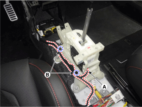
|
| 7. | Remove the shift lever (A) after loosening the mounting bolts. Tightening torque : 8.8 - 13.7 N.m (0.9 - 1.4 kgf.m, 6.5 - 10.1 lb-ft) |
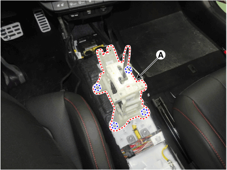
|
| 1. | To install, reverse the removal procedure. | •
| Before installing, check that the shift lever and manual control lever are placed in the "N" position. |
|
| •
| When assembling shift cable, the projection (A) must face upwards. 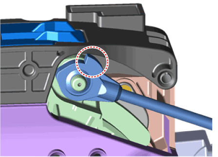
|
| •
| When assembling the snap pin, be careful about the correct direction. 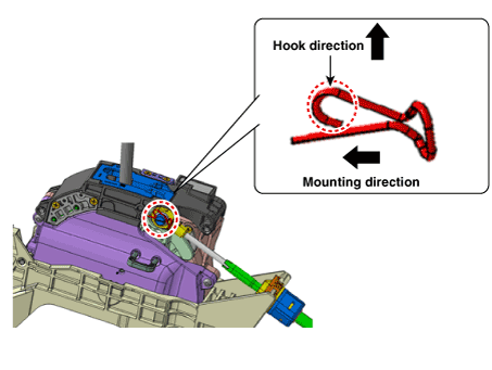
|
|
|
Shift Cable
Components and components location

1. Shift lever knob & boots assembly
2. Shift lever assembly
3. Shift cable
| 4. Manual control lever
5. Shift cable retainer
|
Repair procedures
| 1. | Remove the air cleaner assembly and air duct. (Refer to Engine Mechnical System - "Air cleaner") |
| 2. | Remove the battery and tray. (Refer to Engine Electrical System - "Battery") |
| 3. | Remove the shift cable (A) from the cable bracket, after loosening the mounting nut. 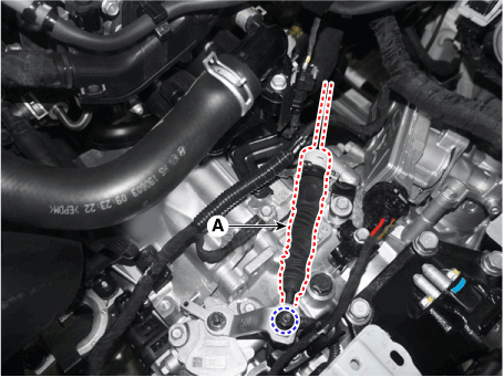
|
| 4. | Remove the shift lever knob & boots (A). 
|
| 5. | Remove the floor console assembly. (Refer to Body - "Floor Console") |
| 6. | Remove the air duct (A) after loosening the bolts. 
|
| 7. | Separate the shift cable sorket (B) after removing the snap pin (A). 
|
| 8. | Remove the retainer (B) by loosening the nuts (A). 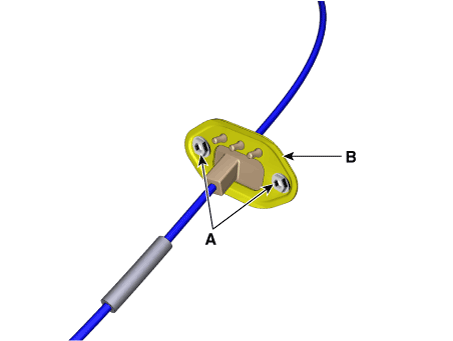
|
| 9. | Remove the shift cable (A) from the vehicle. 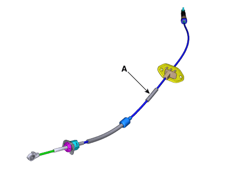
|
| 1. | Install the retainer (B) and then tighten the nut (A). Tightening torque : 11.8 - 14.7 N.m (1.2 - 1.5 kgf.m, 8.7 - 10.8 lb-ft) |

|
| 2. | Install the shift cable sorket (B) and then fix the snap pin (A). 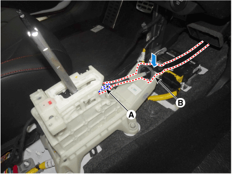
| •
| Before installing, check that the shift lever and manual control lever are placed in the "N" position. |
| •
| When assembling shift cable, the projection (A) must face upwards. 
|
| •
| When assembling the snap pin, be careful about the correct direction. 
|
|
|
| 3. | Install the air duct (A). 
|
| 4. | Install the floor console assembly. (Refer to Body - "Floor Console") |
| 5. | Install the shift lever knob & boots (A). 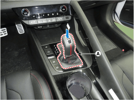
|
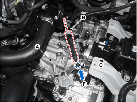
| 6. | Align the hole in the manual control lever with the "N" position hole of the inhibitor switch and then insert the inhibitor switch guide pin (SST No. : 09480 - A3800) (A) in the matched hole. |
| 7. | Push shift cable (B) lightly to "F" direction shown to eliminate free play of shift cable. |
| 8. | Tighten the nut (C) with the specified torque. Tightening torque : 9.8 - 13.7 N.m (1.0 - 1.4 kgf.m, 7.2 - 10.1 lb-ft) |
|
| 9. | Remove the inhibitor switch guide pin (SST No.:09480-A3800) from the hole. |
| 10. | Install the battery and tray. (Refer to Engine Electrical System - "Battery") |
| 11. | Install the air cleaner assembly and air duct. (Refer to Engine Mechnical System - "Air cleaner") | •
| Check that operating surely at each range of the inhibitor switch corresponding to each position of shift lever. |
|
|
DCT (Dual Clutch Transmission)
Components and components location
Components1. DCT (Dual Clutch Transmission) assembly2. DCT support bracket3. Roll rod support bracket
Repair procedures
R ...
Description and operation
Description•
Components location : DCT (Dual Clutch Transmission)•
Function
The dual clutch is in ...
 Hyundai Elantra CN7: Dual Clutch Transmission Control System


