 Hyundai Elantra CN7: Dual Clutch System
Description and operation
| Description |
| • |
Components location : DCT (Dual Clutch Transmission) |
| • |
Function
The dual clutch is installed within the transmission. The dual clutch comprises an odd clutch and an even clutch. The odd clutch transfers and cuts off engine power to the transmission when shifting odd gears. The even clutch transfers and cuts off engine power to the transmission when shifting even gears. |
Dual Clutch Assembly
Components and components location
| Components |
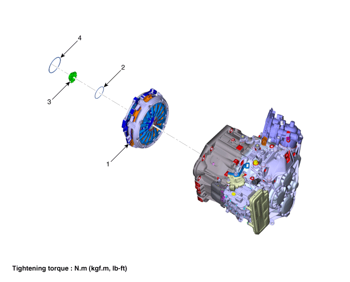
| 1. Dual clutch assembly 2. Snap ring | 3. Spline hub 4. Retaining ring |
Repair procedures
| Removal |
| 1. | Remove the dual clutch transmission from the vehicle. (Refer to Dual Clutch System - "Repair procedures") |
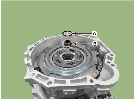
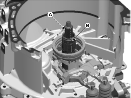
| 2. | Remove the retaining (A) and then removing the spline hub (B).
|
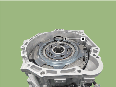
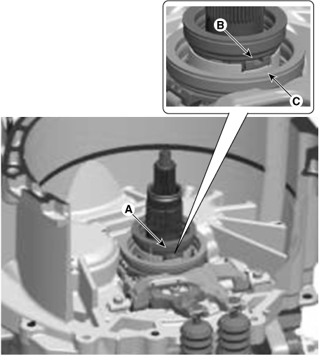
| 3. | Remove the snap ring (A).
|
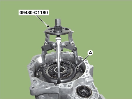
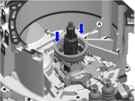
| 4. | Remove the dual clutch assembly (A) by using the special service tool [SST No.: 09430-C1180].
|
| Installation |
|
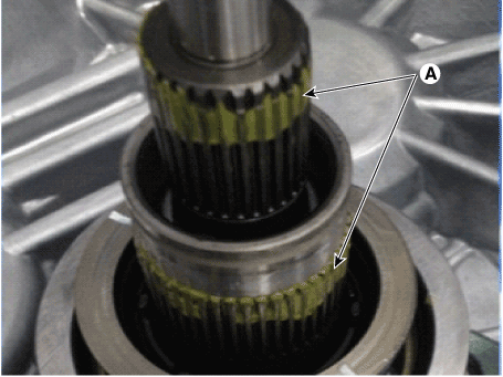
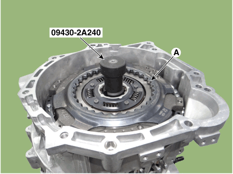
| 1. | Install the SST (No.:09430-2A240) on the support bearing within the dual clutch assembly (A).
|
| 2. | Install the SST (No. : 09430-2A240) on the clutch housing side. |
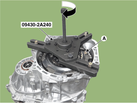
| 3. | Install the dual clutch assembly (A) using the SST (No. : 09430-2A240).
|
| 4. | Install the snap ring (A).
|
| 5. | Install the spline hub (B) and the install the snap ring (A).
|
| 6. | Perform the work procedures for abrasion compensation reset after installing the new dual clutch assembly. (Refer to Clutch Actuator Assembly - "Adjustment") |
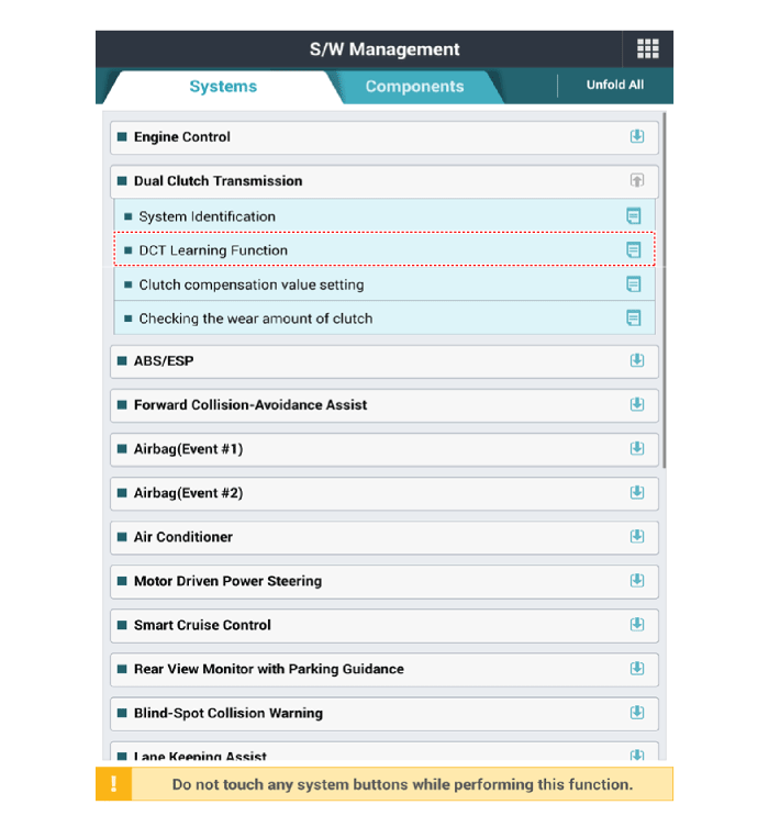
| 7. | Perform the clutch touch point learning procedure using the diagnostic tool after replacing the dual clutch assembly.
|
Clutch Engagement Fork and Engagement Bearing
Components and components location
| Components |
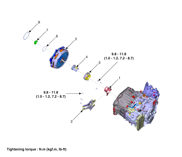
| 1. Engagement bearing sleeve 2. Clutch engagement fork 3. Engagement bearing 1 (Odd) 4. Engagement bearing 2 (Even) | 5. Dual clutch assembly 6. Snap ring 7. Spline hub 8. Retaining ring |
Repair procedures
| Removal |
| 1. | Remove the dual clutch transmission from the vehicle. (Refer to DCT System - "DCT) |
| 2. | Remove the dual clutch assembly. (Refer to Dual Clutch System - "Double Clutch Assembly") |
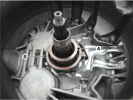
| 3. | Remove the clutch engagement bearing 2 (A) and 1 (B).
|
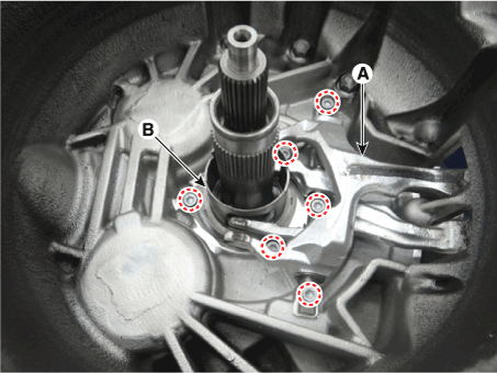
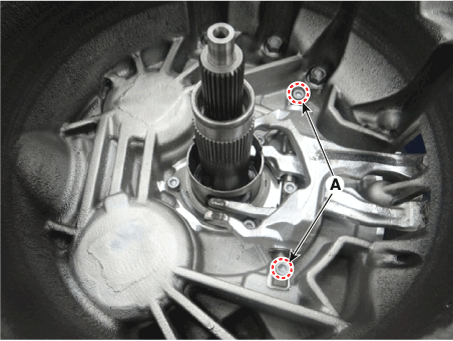
| 4. | Remove the clutch engagement fork (A) and engagement bearing sleeve (B).
|
| Installation |
|
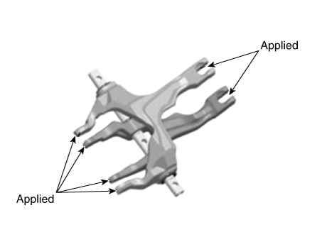
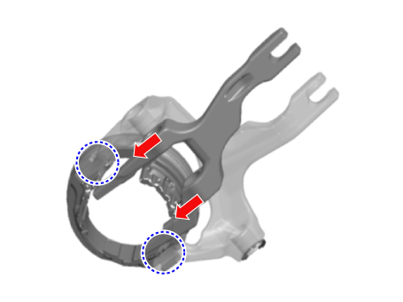
| 1. | Install the clutch engagement fork (A) and engagement bearing sleeve (B).
|
| 2. | Install the engagement bearing 1 (A).
|
| 3. | Install the engagement bearing 2 (A).
|

