Hyundai Elantra CN7: Windshield Wiper/Washer
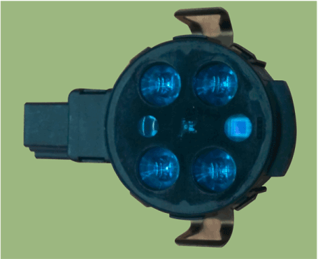
Components and components location
| Component Location |
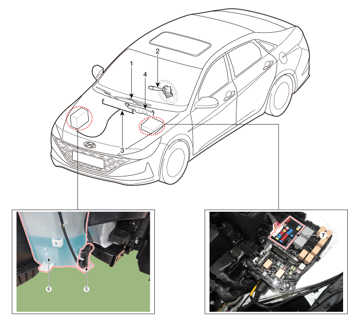
| 1. Windshield wiper arm & blade 2. Wiper & washer switch 3. Windshield washer hose & nolzzle 4. Washer motor & linkage assembly | 5. Washer motor 6. Washer reservoir 7. Wiper/Washer relay (Built - in PCB block) |
Windshield Wiper-Washer Switch
Repair procedures
| Removal |
| 1. | Disconnect the negative (-) battery terminal. |
| 2. | If it is necessary to remove multifunction switch assembly, remove the steering wheel. (Steering System - "Steering Wheel") |
| 3. | Remove the steering column upper shrouds. (Refer to Body - "Steering Column Shroud Panel") |
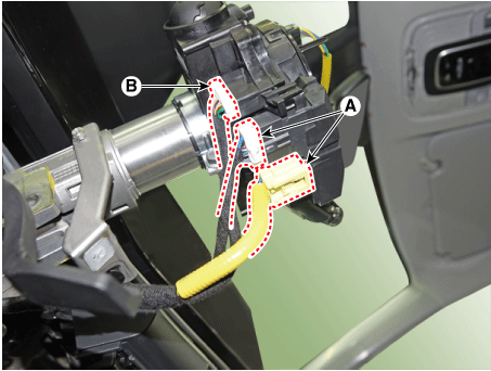
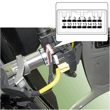
| 4. | Disconnect the clock spring connector (A) and multifunction switch connector (B).
|
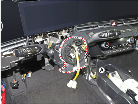
| 5. | Remove the clock spring (A).
|
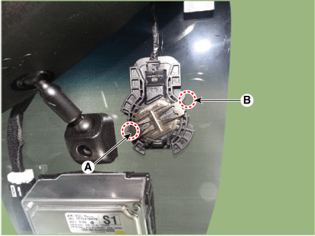
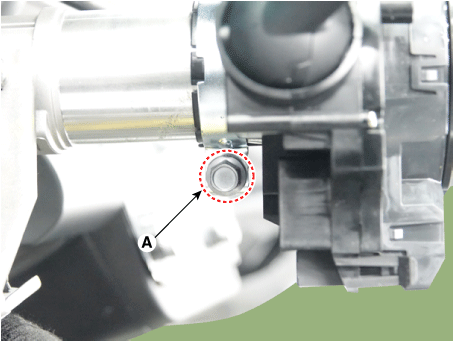
| 6. | Loosen the clamp (A) and remove the multifunction switch assembly (A).
|
| Installation |
| 1. | Install the multifunction switch. |
| 2. | Install the clock spring and steering wheel. |
| 3. | Install the steering column upper and lower shrouds. |
| 4. | Install the steering wheel. |
| Inspection |
Windshield Wiper/Washer Switch Inspection
| 1. | Check for continuity between the terminals in each switch position as shown below.
|
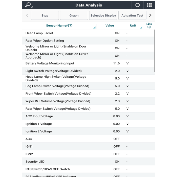
Inspection (With Diagnostic tool)
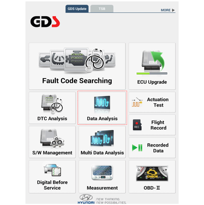
| 1. | In the body electrical system, failure can be quickly diagnosed by using the vehicle diagnostic system (Diagnostic tool). The diagnostic system (Diagnostic tool) provides the following information.
|
| 2. | If diagnose the vehicle by Diagnostic tool, select "DTC Analysis" and "Vehicle".
|

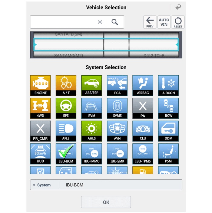
| 3. | If check current status, select the "Data Analysis" and "Car model".
|
| 4. | Select the 'IBU_BCM' to search the current state of the input/output data.
|
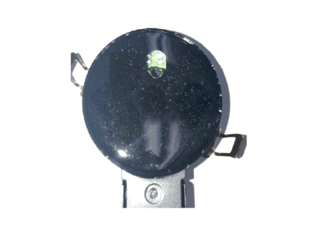
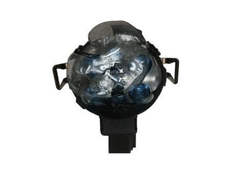
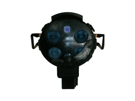
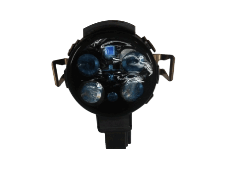
Front Wiper Motor
Components and components location
| Component Location |
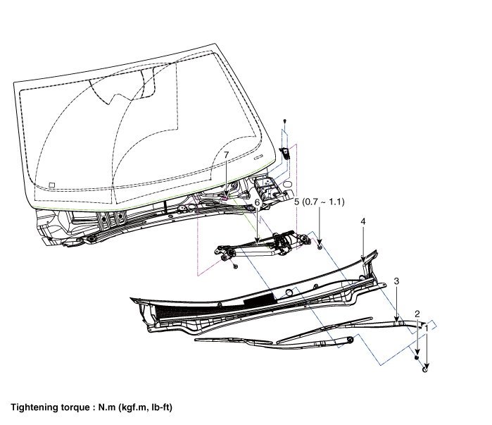
| 1. Cap 2. Nut 3. Wiper arm & blade 4. Cowl top cover | 5. Bolt 6. Wiper motor & linkage assembly 7. Wiper motor connector |
Repair procedures
| Removal |
| 1. | Disconnect the negative (-) battery terminal. |
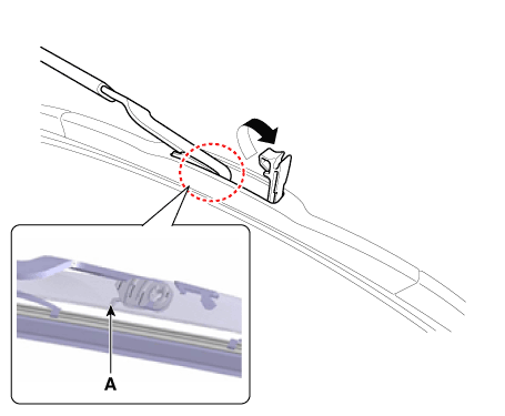
| 2. | If necessary, release the wiper blade fixing clip by pulling up and remove the wiper blade from the inside radius of wiper arm.
|
| 3. | Remove the cowl top cover. (Refer to Body - "Cowl Top Cover") |
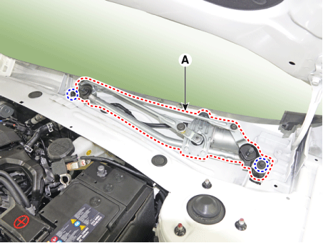
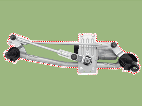
| 4. | Remove the windshield wiper motor and linkage assembly (A) after removing 2 bolts.
|
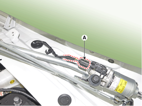
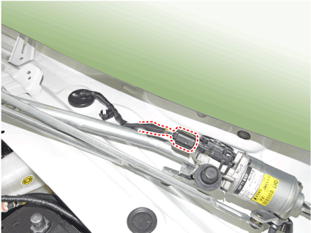
| 5. | Disconnect the wiper motor connector (A) from the wiper motor & linkage assembly.
|
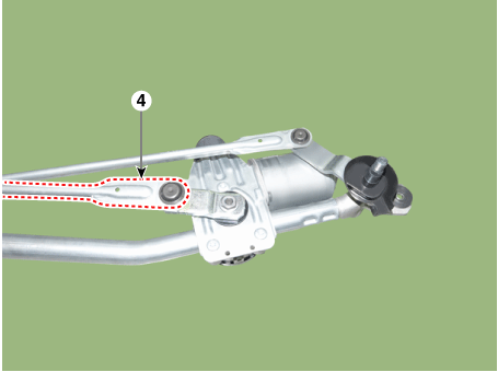
| 6. | Hold the wiper motor crank arm and remove the upper linkage (A) from the wiper motor crank arm.
|

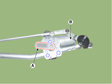
| 7. | Loosen the mounting nut, screws and remove the crank arm (A) and wiper motor (B).
|
| Installation |
| 1. | Install the wiper motor and linkage assembly and then connect the wiper motor connector.
|
| 2. | Install the crank arm.
|
| 3. | Install the cowl top cover. |
| 4. | Install the windshield wiper arm and blade.
|

| 5. | Install the wiper arm and blade to the specified position.
|
| Inspection |
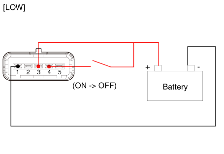
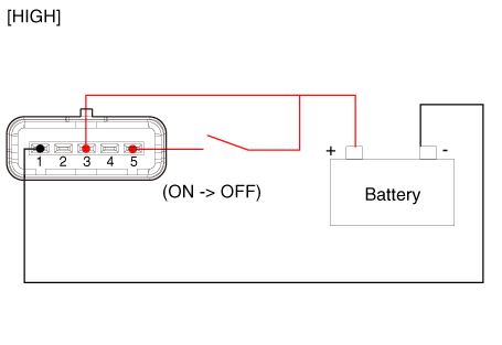
| 1. | Remove the connector from the wiper motor.
|
| 2. | Attach the positive (+) lead from the battery to terminal 3 and the negative (-) lead to terminal 5.
|
Diagnosis with Diagnostic tool
| 1. | In the body electrical system, failure can be quickly diagnosed by using the vehicle diagnostic system (Diagnostic tool). The diagnostic system (Diagnostic tool) provides the following information.
|
| 2. | If diagnose the vehicle by Diagnostic tool, select "DTC Analysis" and "Vehicle".
|
| 3. | Select the 'Data Analysis'.
|
| 4. | Select the 'IBU_BCM' to search the current state of the input/output data.
|
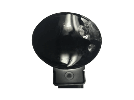
Front Washer Motor
Repair procedures
| Inspection |
Front Washer Motor
| 1. | With the washer motor connected to the reservoir tank, fill the reservoir tank with water.
|
| 2. | Connect positive (+) battery cables to terminal 2 and negative (-) battery cables to terminal 1 respectively. |
| 3. | Check that the motor operates normally and the washer motor runs and water sprays from the front nozzles. |
| 4. | If they are abnormal, replace the washer motor.
|
| Removal |
|
| 1. | Disconnect the negative (-) battery terminal. |
| 2. | Remove the right front wheel guard. (Refer to Body - "Front Wheel Guard") |
| 3. | Remove the engine room under cover (Refer to Engine Mechanical System - "Engine Room Under Cover") |
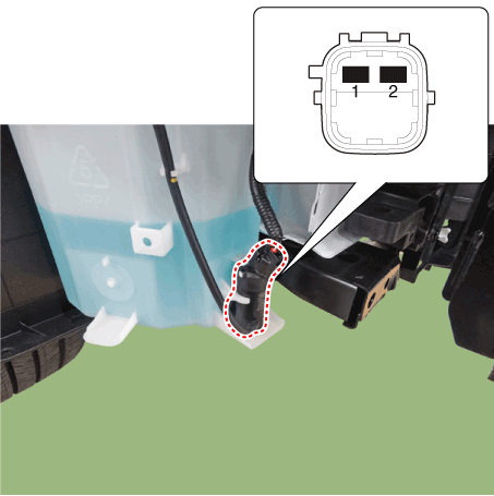
| 4. | Remove the washer hose (B) and disconnect the washer motor connector (A).
|
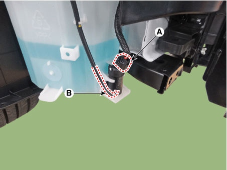
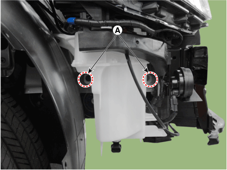
| 5. | Remove the reservoir washer inlet (A) after loosening the mounting bolt.
|
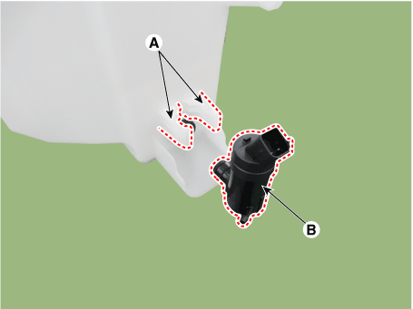
| 6. | Remove the washer motor (B) after disengaging the fixed hook (A).
|
| Installation |
| 1. | Install the washer reservoir.
|
| 2. | Install the washer motor. |
| 3. | Install the washer hose. |
| 4. | Connect the washer motor connector and level sensor connector. |
| 5. | Install the tire and wheel guide cover. (Refer to Body - "Front Wheel Guard") |
| 6. | Install the engine room under cover. (Refer to Engine Mechanical System - "Engine Room Under Cover") |
| 7. | Check the washer motor operation. |
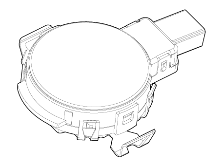
Rain Sensor
Description and operation
| Description |
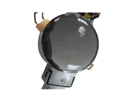
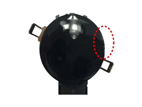
Integrated Rain Sensor
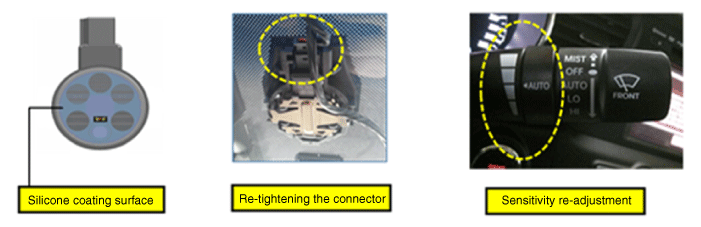
Integrated rain sensor (A) controls three systems: front wiper, auto-light, and central air conditioner.
| 1. | Wiper Control System When "AUTO" switch signal is received from the multi-function switch on the right, the integrated rain sensor detects the amount of rainfall. The sensor is installed inside the upper part of the front window for wiper motor control. This system automatically controls the operation duration and speed of the wiper depending on the measured amount of rainfall even if the driver does not operate the wiper switch.
|
| Functions and Operating Principles |
Basic Principle
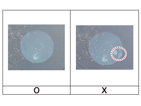
| 1. | Detecting the amount of rainfall The light (beam) emitted from light emitting diodes (LED) is totally reflected on the external surface of the windshield and comes back to the photo diodes. When there is water on the external surface of the windshield, the light is optically separated and reflected partially and the remaining brightness is measured by the photo diodes. Water remaining on the windshield results in the light being not totally reflected. The loss of brightness due to this indicates how much the glass surface is wet. |
Interference
Rain sensor might malfunction due to the interferences listed below.
| 1. | Dust on the measuring surface and other surfaces on the light path (surface of light emitting diodes and photo diodes, fiber optics, bracket, and glass surface of windshield joint area) weakens the received light. |
| 2. | Movement of windshield and bracket |
| 3. | Movement of bracket due to vibration |
| 4. | Damaged wiper blade |
|
Automatic Operation
| 1. | Operational status of rain sensor
|
Safety Function
| 1. | When there is ice or foreign matter in the detecting area, integrated rain sensor cannot recognize the condition for operation correctly. |
Detecting Special Conditions
| 1. | Rain sensor
|
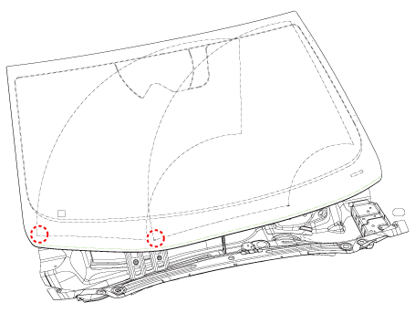
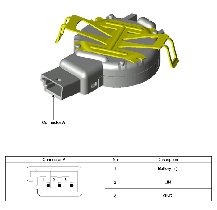
Components and components location
| Components and Components Location |
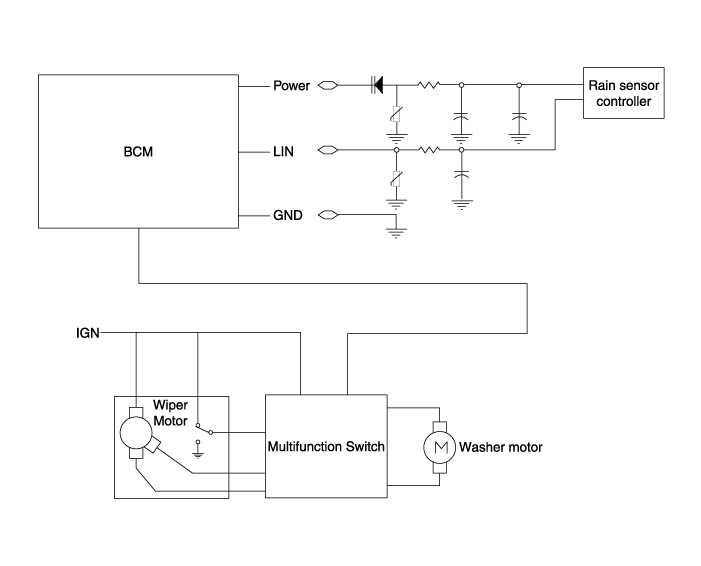
Schematic diagrams
| Circuit Diagram |
Repair procedures
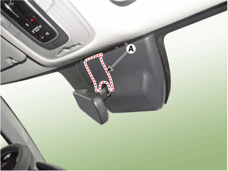
| Removal |
|
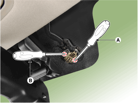
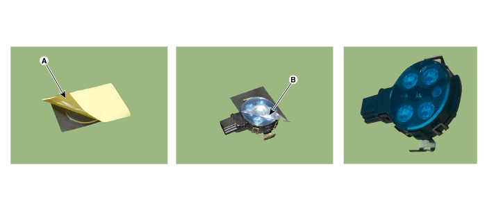
| 1. | Remove the inside rear view mirror cover (A).
|
| 2. | Using a remover and remove the rain sensor cover (A).
|
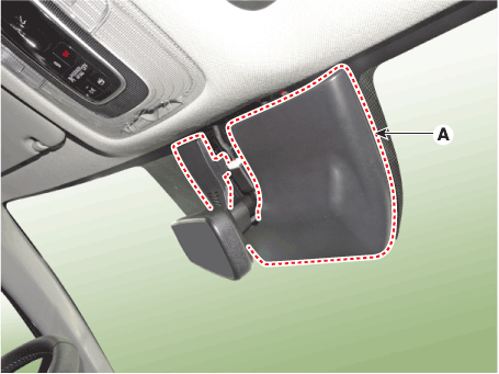
| 3. | Be careful not to damage the cover latch by applying excessive force. To remove the latch, pull aside the latch using the cover hole with a small flat - blade screwdriver (A).
|
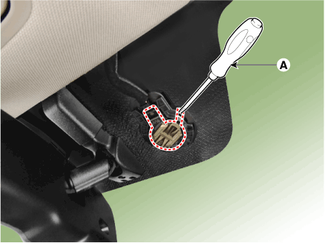
| 4. | Remove the rain sensor.
|
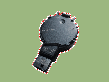
| Installation |
| |||||||||||||||||||||||||||||||||||||||||||||||||||||||
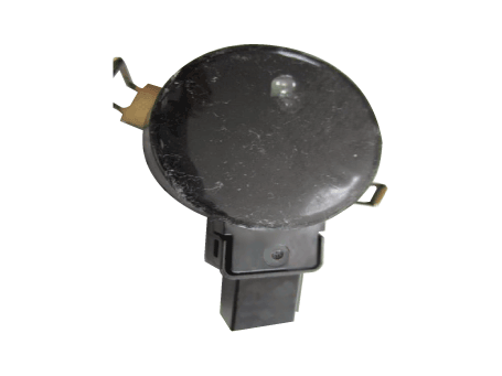
| 1. | Connect the rain sensor connector. |
| 2. | Push one of the latch of spring arm (A) down until it snaps and you hear a click sound. And then push the latch of second spring arm (B) for keeping the sensor in right position.
|