Engine removal is not required for this procedure.
| • |
Use fender covers to avoid damaging painted surfaces.
|
| • |
To avoid damage, unplug the wiring connectors carefully
while holding the connector portion.
|
|
|
Mark all wiring and hoses to avoid misconnection.
|
| 1. |
Disconnect the battery negative terminal. (Refer to Engine and
transaxle assembly in this group)
|
| 2. |
Remove the RH front wheel. (Refer to SS group – “Wheel”)
|
| 3. |
Remove the RH under cover. (Refer to Engine and transaxle assembly
in this group)
|
| 4. |
Remove the engine cover. (Refer to Engine and transaxle assembly
in this group)
|
| 5. |
Disconnect the wiring connectors and harness clamps, and then
remove the wiring and protectors from the cylinder head cover.
| (1) |
The intake OCV (Oil control valve) connector (A)

|
| (2) |
The exhaust OCV (Oil control valve) connector (A)

|
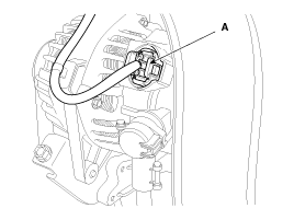
| (3) |
The alternator connector (A)

|
| (4) |
The ignition coil connectors (A)

|
| (5) |
The intake CMPS (Camshaft position sensor) connector (A)
|
| (6) |
The exhaust CMPS (Camshaft position sensor) connector
(B)

|
|
| 6. |
Disconnect the breather hose (A).

|
| 7. |
Disconnect the PCV (Positive crankcase ventilation) hose (A).

|
| 8. |
Remove the ignition coils (A).

|
| 9. |
Remove the engine oil level gauge (A).

|
| 10. |
Remove the cylinder head cover (A).

|
Unfasten the bolts in the sequence as shown.
|

|
| 11. |
Drain engine oil and remove the oil pan. (Refer to Lubrication
system in this group)
|
| 12. |
Remove the engine mounting support bracket.
| (1) |
Set the jack to the edge of the lower crankcase.
|
Put the wooden block between lower crankcase and
jack.
|
|
Be careful not to damage the oil screen.
|
|
| (2) |
Disconnect the engine ground line (A).
|
| (3) |
Remove the engine mounting support bracket (B).

|
|
| 13. |
Remove the drive belt.
| (1) |
Loosen the alternator mounting bolts (A).
|
| (2) |
Loosen the tension by turning the tension adjusting bolt
(B) counterclockwise.
|
| (3) |
Remove the drive belt (C).

|
|
| 14. |
Remove the front engine hanger (A).

|
| 15. |
Remove the alternator (A). (Refer to EE group – “Alternator”)

|
| 16. |
Remove the water pump pulley (A).

|
| 17. |
Set No.1 cylinder to TDC (Top dead center) on compression stroke.
| (1) |
Turn the crankshaft pulley and align its groove with the
timing mark of the timing chain cover.

|
| (2) |
Check that the TDC marks of the intake and exhaust CVVT
sprockets are in straight line on the cylinder head surface
as shown in the illustration. If not, turn the crankshaft by
one revolution (360°) more.

|
Do not turn the crankshaft pulley counterclockwise.
|
|
|
| 18. |
Remove the crankshaft damper pulley (A).

|
Do not press the pulley or apply the excessive force to
prevent the rubber part from being deformed.
|
|
There are two methods to hold the ring gear when removing
the crankshaft damper pullly.
| • |
Install the SST (09231-2B100) to hold the ring
gear after removing the starter.

|
| • |
Install the SST (09231-3D100) to hold the ring
gear after removing the service cover.
|
| 1. |
Remove the air guard (A).

|
| 2. |
Remove the two transaxle mounting bolts (A) and
the service cover (B) on the bottom of the lower crankcase.

|
| 3. |
Adjust the length of the holder (A) so that the
grooves of the holder puts into the ring gears (B) at
the closest position.
|
| 4. |
Adjust the angle and length of the links (C) so
that the two transaxle mounting bolts can be fastened
into the original mounted holes.

|
| 5. |
Install the SST using the two transaxle mounting
bolts. Tighten the bolts and nuts of the holder and
links securely.

|
|
|
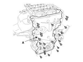
| 19. |
Remove the timing chain cover (A) by gently prying the gaps between
the cylinder head and cylinder block.

|
Be careful not to damage the contact surfaces of cylinder
block, cylinder head and timing chain cover.
|
|
| 20. |
Remove the timing chain tensioner (A).

| • |
Do not reuse the detached tensioner.
|
| • |
If need to reuse the tensioner, remove the tensioner,
make the piston (A) to protrude maximally, push the
piston (A) to the end, and then mount the stopper pin.
At this time, the tensioner fixing pin should
be placed in the same way as when the product was first
delivered from the factory.
|


|
|
| 21. |
Remove the timing chain tensioner arm (A).

|
| 22. |
Remove the timing chain (A).

|
| 23. |
Remove the timing chain guide (A).

|
Sprockets, Chain Tensioner, Chain Guide, Chain Tensioner Arm
1.
Check the CVVT sprocket and crankshaft sprocket for abnormal wear,
cracks, or damage. Replace if necessary.
...
 Hyundai Elantra MD/UD: Removal


