Description and operation
Rear Corner Radar is a system that measures the relative speed and distance from the following vehicles by using two electromagnetic wave radar sensors attached to the rear bumper, and detects any vehicle within the blind spot zone and gives off alarm.
System Interface
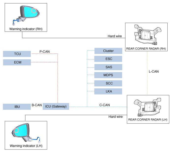
It is a system that provides detecting, warning (visual and audible) and controlling the obstacle in the blind spots of the rear corner side while driving by measuring the distance and speed of the rear corner vehicles using the radar waves emitted from the 2 rear corner radar sensors mounted inside the rear bumper. | •
| BCW(Blind-spot Collision Warning): The BCW detects the vehicle approaching at high speed from the blind spot and rear of your vehicle while driving and warns the driver. |
| •
| BCA(Blind-Spot Collision-Avoidance Assist): The BCA assists to avoid collision with the vehicle approaching from the blind spot by controlling the brake partially when your vehicle departs the lane. |
| •
| SEW (Safe Exit Warning): The SEW warns the collision with the vehicle in the back when getting off the vehicle. |
| •
| RCCW (Rear Cross-Traffic Collision Warning): The RCCW detects the vehicles approaching from the left and right sides and warns the driver while your vehicle is reversing. |
| •
| RCCA (Rear Cross-Traffic Collision-Avoidance Assist): The RCCA assists to avoid collision with the vehicles approaching from the left and right sides by controlling the brake while your vehicle is reversing. |
|
System Function
The Rear Corner Radar (RR_C_RDR) supports the functions below using the detecting information (vehicle/2-wheeled vehicle) of the rear corner radar, recognition information (lane) of the front camera and the vehicle signal information (CAN communication).
| 1. | BCW (Blind-Spot Collision Warning): It detects the vehicles approaching from the blind spot and informs the driver of a possible collision with a warning message and audible warning while driving at the speed of over specific speed. Also, when you are driving forward to exit the vehicle, it helps braking to avoid collision if the system judges that there is a collision risk with the vehicle approaching from the rear corner. 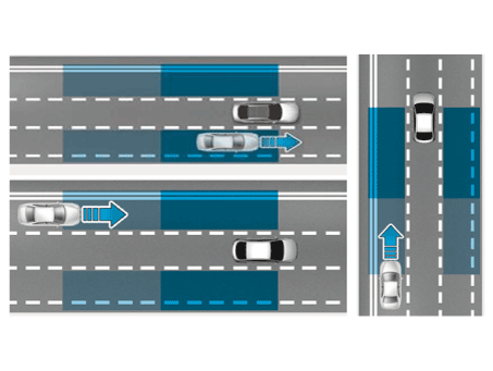
|
| 2. | BCA (Blind-Spot Collision-Avoid Assist): It assists the collision avoidance by controlling the brake partially if the system judges that there is a collision risk with the vehicle approaching from the rear corner when changing lanes by detecting the lane ahead. Also, when you are driving forward to exit the vehicle, it helps braking to avoid collision if the system judges that there is a collision risk with the vehicle approaching from the rear corner. 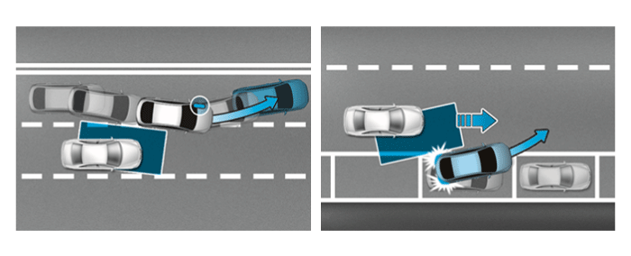
|
| 3. | SEW (Safety Exit Warning): It warns the driver with a warning message and an audible warning if the system judges that there is a collision risk with the vehicle approaching from the rear corner when a passenger opens door to leave a vehicle after vehicle is stopped. 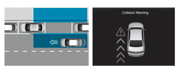
|
| 4. | RCCW (Rear Cross-Traffic Collision Warning): It warns the driver with a warning message and an audible warning if the system judges that there is a collision risk with the vehicle approaching from the left and right sides while your vehicle is reversing. 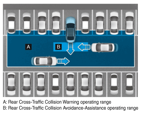
|
| 5. | RCCA (Rear Cross-Traffic Collision-Avoidance Assist): It warns the driver with a warning message and an audible warning and helps braking to avoid collision if the system judges that there is a collision risk with the vehicle approaching from the left and right sides while your vehicle is reversing. 
|
Warning Condition
Blind-Spot Collision Warning (BCW)
| 1. | BCW activating conditions | (1) | User Setting Menu (USM): Select 'Driver Assistance' → 'Blind-Spot Safety' → 'Blind-Spot Collision Warning' |
| (2) | Vehicle speed: 20 km/h or faster |
| (3) | Curvature radius: 100m or more |
| (4) | Relative vehicle speed: -15 ~ 255 km/h |
("-" means overtaking the preceding vehicle) |
| 2. | BCW deactivating conditions | (1) | Vehicle speed: 17 km/h or slower |
| (2) | Curvature radius: 70m or less |
| (3) | Relative vehicle speed: All cases except -15 ~ 255 km/h |
("-" means overtaking the preceding vehicle) |
| 3. | Warning zone A ~ B: Blind spot zone B ~ C: Detecting range for vehicles approaching at high speed 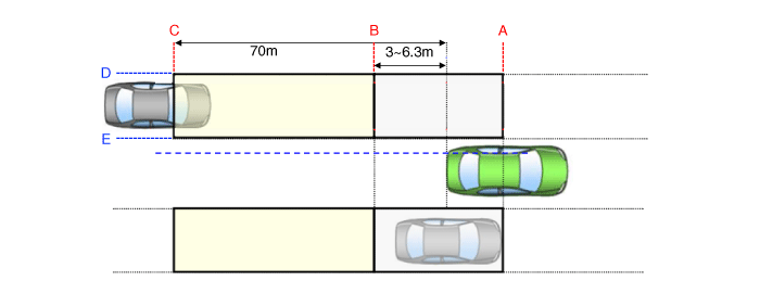
|
| 4. | Conditions for BCW warning ON A. Driver's position in your vehicle B. 3 ~ 6.3m from the rear bumper end D. 70kph or less: 3m + (your vehicle width/2) 80kph or more: 3.4m + (your vehicle width/2) 70kph≤your vehicle speed≤80kph: Follows the standard of your vehicle speed entered among 70kph/80kph E. 0.4 from the center of your vehicle + (your vehicle width/2) |
| (1) | The entire body of the target vehicle is located behind the line A. |
| (2) | Any part of the target vehicle pass the line B. |
| (3) | Any part of the target vehicle passes the line D and Hysteresis In. |
| (4) | The entire part of the target vehicle passes the line E and Hysteresis In. 
|
|
| 5. | Conditions for BCW warning OFF A. Driver's position in your vehicle B. 4 ~ 7.3m from the rear bumper end D. 70kph or less: 3.7m + (your vehicle width/2) 80kph or more: 4.1m + (your vehicle width/2) 70kph≤your vehicle speed≤80kph: Follows the standard of your vehicle speed entered among 70kph/80kph E. 0.7 from the center of your vehicle + (your vehicle width/2) |
| (1) | The entire body of the target vehicle moves before the line A. |
| (2) | The entire body of the target vehicle moves behind the line B. |
| (3) | The entire body of the target vehicle passes the line D and Hysteresis Out. |
| (4) | The entire part of the target vehicle passes the line E and Hysteresis Out. 
|
|
| 6. | Warning ON conditions for vehicles approaching at high speed B. 3 ~ 6.3m from the rear bumper end C. Within 30 ~ 70m from the rear bumper end D. 70kph or less: 3m + (your vehicle width/2) 80kph or more: 3.4m + (your vehicle width/2) 70kph≤your vehicle speed≤80kph: Follows the standard of your vehicle speed entered among 70kph/80kph E. 0.4 from the center of your vehicle (your vehicle width/2) |
| (1) | The entire body of the target vehicle is located behind the line B. |
| (2) | Any part of the target vehicle pass the line C. |
| (3) | Any part of the target vehicle passes the line D and Hysteresis In. |
| (4) | The entire part of the target vehicle passes the line E and Hysteresis In. |
| (5) | In the all above condition, TTC(Time to Collision) is not less than 4.5 sec. 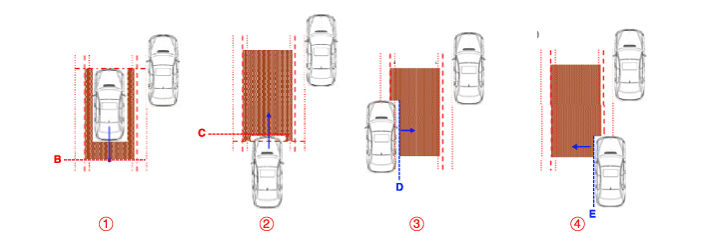
|
|
| 7. | Warning OFF conditions for vehicles approaching at high speed B. 30 ~ 70m from the rear bumper end D. 70kph or less: 3.7m + (your vehicle width/2) 80kph or more: 4.1m + (your vehicle width/2) 70kph≤your vehicle speed≤80kph: Follows the standard of your vehicle speed entered among 70kph/80kph E. 0.7 from the center of the vehicle + (your vehicle width/2) |
| (1) | If the entire body of the target vehicle is out of the line C |
| (2) | If the entire body of the target vehicle crosses the line D |
| (3) | If the entire body of the target vehicle crosses the line E |
| (4) | When the TTI (Time To Intersection) exceeds 4.5 seconds (normal) / 3.8 seconds (slow) |
| (5) | The right side area of the vehicle is symmetrical |
|
| 8. | System control prohibition | (1) | If the entire surface of rear corner radar is covered with foreign materials: System conditions - Blockage message is displayed. | •
| If the sensing area on the rear bumper is contaminated by snow, mud or stickers, sensor detecting performance may deteriorate. |
|
|
| (2) | If the mounting angle of the rear corner radar is distorted by the external shock: DTC is sent |
| (3) | When BCW system fails: DTC is sent | •
| If the surroundings of the rear bumper are contaminated by the foreign material interfering with the rear corner radar, an error message may be sent but it is not the BCW system failure. |
|
|
|
Blind-Spot Collision-Avoidance Assist (BCA)
| 1. | BCA activating conditions | (1) | User Setting Menu (USM): Select 'Driver Assistance' → 'Blind-Spot Safety' → 'Blind-Spot Collision-Avoidance-Assist' |
| (2) | Vehicle speed: 60 km/h ~ 200 km/h |
| (3) | Curvature radius: 600m or more |
| (4) | Both lanes are recognized |
| (5) | Other functions related with ESC not working |
|
| 2. | BCA deactivating conditions | (1) | Vehicle speed: 55 km/h or slower, 210 km/h or faster |
| (2) | Curvature radius: 570m or less |
| (3) | Other functions related with ESC working |
|
| 3. | Warning zone (driving condition) 
|
| 4. | Conditions for BCA (driving condition) control ON A. Distance from the rear bumper end to the driver's eyes. B. 1.5m from the rear of your vehicle D. 2.2m from left side of your vehicle + (your vehicle width/2) E. 0.4m from left side of your vehicle + (your vehicle width/2) |
| (1) | When the entire body of the target vehicle enters inside the line A, B, C, D area |
| (2) | The right side area of the vehicle is symmetrical |
|
| 5. | Conditions for BCA (driving condition) control OFF A. Distance from the rear bumper end to the driver's eyes - 1m B. 1.7m from the rear of your vehicle D. 2.4m from the left side of your vehicle + (your vehicle width/2) E. 0.7m from the left side of your vehicle + (your vehicle width/2) |
| (1) | When the entire body of the target vehicle moves out of the line A, B, C, D area |
| (2) | The right side area of the vehicle is symmetrical |
|
| 6. | Conditions for BCA (pulling out/exit condition) control 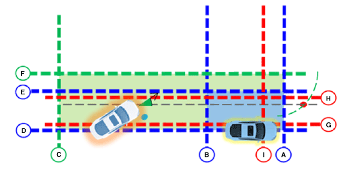
A. 0.2m from the front of your vehicle B. 4m from the rear of your vehicle C. 60m from the rear of your vehicle D. 0m from your vehicle E. 1m from the left side of your vehicle + (your vehicle width/2) F. 1.5m from the left side of your vehicle (check variable condition) + (your vehicle width/2) |
* Condition 1 | (1) | When the entire body of the target vehicle is positioned inside the line A, B, D, F area |
| (2) | When approaching angle of the opponent vehicle is between -55° ~ 55° based on the driving direction |
| (3) | When the cross point of the route is between the D and E |
| (4) | The right side area of the vehicle is symmetrical |
* Condition 2 | (5) | When the entire body of the target vehicle is positioned inside the line A, C, D, F area |
| (6) | When approaching angle of the opponent vehicle is between -55° ~ 55° based on the driving direction |
| (7) | When the cross point of the route is between the D and E |
| (8) | When meets the TTI (Time to Intersection) variable condition |
| (9) | The right side area of the vehicle is symmetrical |
|
Rear Cross-Traffic Collision Warning (RCCW)
| 1. | RCCW activating conditions | (1) | User Setting Menu (USM): Select 'Driver Assist Parking Safety' → 'Rear Cross-Traffic Safety' |
| (2) | Shift lever position: R |
| (3) | Vehicle speed: 0 ~ 8 km/h |
| (4) | Speed of opponent vehicle: 5 km/h or faster |
|
| 2. | RCCW deactivating condition | (1) | Vehicle speed: 10 km/h or faster |
|
| 3. | Warning zone 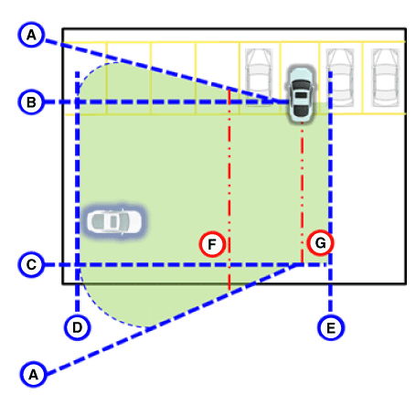
|
| 4. | RCCW warning conditions | (1) | Condition: A warning occurs when the collision risk with the vehicle approaching from the rear corner is detected while pulling out your vehicle backward. |
| (2) | Warning occurs within 3.5~2.1 seconds (normal)/2.9~2.1 seconds (slow) based on the TTI (Time To Intersection) | •
| It is the estimated collision time calculated by using the relative distance/speed, which means that a collision may occur after estimated collision time. (It varies depending on the relative speed of the approaching vehicle) |
|
A. Vehicles approaching at a diagonal angle of 35° A’ Vehicles approaching at a diagonal angle of 55° B 2m from the rear bumper end C 6m from the rear bumper end D 25m of distance from the center line of the vehicle + (your vehicle width/2) E. 1m of distance from the center line of the vehicle + (your vehicle width/2) |
|
| (3) | When a part of the target vehicle enters inside the line A, B, C, D, E area |
| (4) | When the driving direction of the target vehicle passes through the F and G |
| (5) | The right side area of the vehicle is symmetrical |
|
Rear Cross-Traffic Collision-Avoidance Assist (RCCA)
| 1. | RCCA activating conditions | (1) | User Setting Menu (USM): Select 'Driver Assist' - 'Parking Safety ' → 'Rear Cross-Traffic Safety' |
| (2) | Shift lever position: R |
| (3) | Vehicle speed: 0 ~ 8 km/h |
| (4) | Speed of opponent vehicle: 5 km/h or faster |
| (5) | Other functions related with ESC not working |
|
| 2. | RCCW deactivating conditions | (1) | Vehicle speed: 10 km/h or faster |
| (2) | Other functions related with ESC working |
|
| 3. | Warning zone 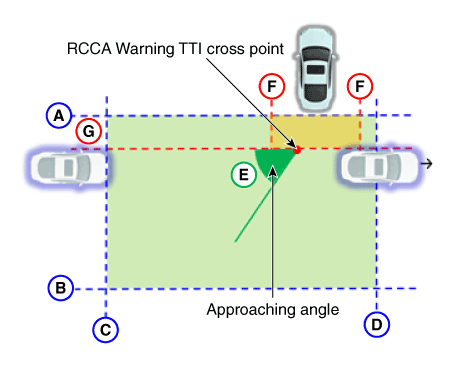
|
| 4. | Conditions for RCCA control | (1) | Warning occurs approximately within 2.1 ~ 3.5 seconds based on the TTI (Time to Intersection) when a target vehicle enters the warning zone. |
| (2) | Refer to conditions below based on the TTI (Time to Intersection) A Rear bumper end B 6m from the rear bumper end C 10m from the center of the vehicle + (your vehicle width/2) D 1m from the center of the vehicle + (your vehicle width/2) E. Based on the transverse of rear bumper of your vehicle / Approaching angle is below 55° F 0.5m from the center of the vehicle + (your vehicle width/2) G Xcp position is -1m from the rear bumper end * Xcp: To the collision position of your vehicle and the target vehicle / Positioned at X direction |
|
| (3) | When a part of the target vehicle enters inside the line F & G area (Selected as a target to be interested if target vehicle enters inside the line A, B, C, D) |
| (4) | When the driving direction of the target vehicle passes through the F and G |
| (5) | In case of the opponent vehicle TTI ≤ 1 second & your vehicle TTI ≤ 2 seconds (varies depending on the vehicle model) |
| (6) | The right side area of the vehicle is symmetrical |
|
Safe Exit Warning / Safe Exit Assist (SEW / SEA)
| 1. | SEW/SEA activating conditions | (1) | User Setting Menu (USM): Select 'Driver Assistance' - 'Blind-spot safety ' - 'Safe Exit Assist' |
| (3) | Vehicle speed: 0 ~ 3 km/h |
| (4) | Speed of opponent vehicle: 5 km/h or faster |
| (5) | Speed of target vehicle: 6 ~ 80 km/h |
|
| 2. | SEW/SEA deactivating condition | (1) | Vehicle speed: 5 km/h or faster |
|
| 3. | Warning zone 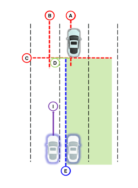
|
| 4. | SEW/SEA warning conditions | (1) | Warning occurs approximately within 2.1 ~ 3.5 seconds based on the TTI (Time to Intersection) when a target vehicle enters the warning zone. |
| (2) | The SEW/SEA warns when time is less than 3 seconds based on the TTI (Time to Intersection) A 0.5m from the center line of your vehicle B 2m from the center line of your vehicle + (your vehicle width/2) C Rear bumper end E Your vehicle width from the center line of your vehicle/2 I -25° ≤ Approaching angle ≤ 25° |
|
| (3) | Line D (warning line): When the line I intersects the line C which is from the line A to line B - Check the items below when BCW/BCA/SEW/SEA/RCCW/RCCA is faulty. (1) Check for the bumper cleanliness: If the bumper is contaminated by snow or dust, the performance may deteriorate. (2) Check for the condition around the bumper: If the metal sticker or foreign material is attached around the rear corner radar, function may not work. (3) Check for the bumper shape or installation state: If the bumper or rear corner radar is not installed properly after the accident, function may not work. (4) If the DTC (C2702, C2703) occurs, check for the bumper, bracket or rear corner radar. | •
| Bumper: Installation state, outer deformation of the bumper |
| •
| Bracket: Installation state, deformation of the bracket |
| •
| Rear corner radar: bad nut tightening, contamination by foreign material |
|
|
|
Troubleshooting
Diagnosis with Diagnostic tool
| 1. | In the body electrical system, failure can be quickly diagnosed by using the vehicle diagnostic system (Diagnostic tool). The diagnostic system (Diagnostic tool) provides the following information. | (1) | Fault Code Searching : Checking failure and code number (DTC) |
| (2) | Data Analysis : Checking the system input/output data state |
| (3) | Actuation test : Checking the system operation condition |
| (4) | S/W Management : Controlling other features including system option setting and zero point adjustment |
|
| 2. | Connect the cable of Diagnostic tool to the data link connector in driver side crash pad lower panel, and turn on the Diagnostic tool. |
| 3. | If diagnose the vehicle by Diagnostic tool, select "DTC Analysis" and "Vehicle". 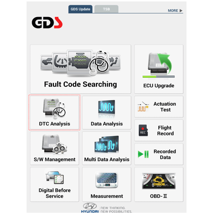
|
| 4. | If check current status, select the "Data Analysis" . 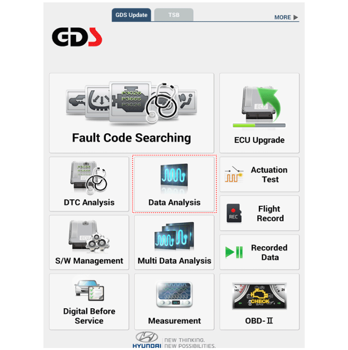
|
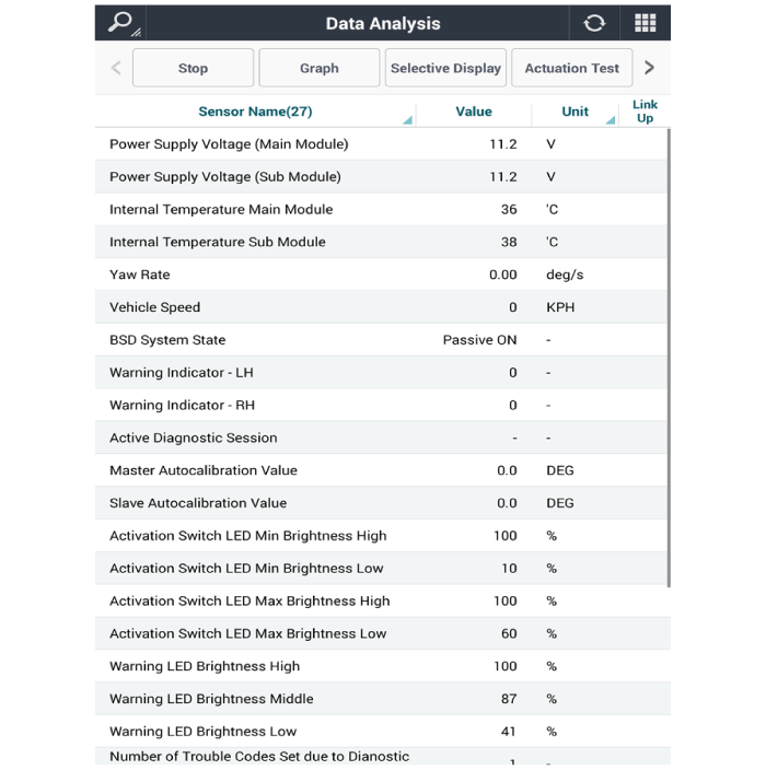
| 5. | Select "BCW", if you want to check current data of BCW system. 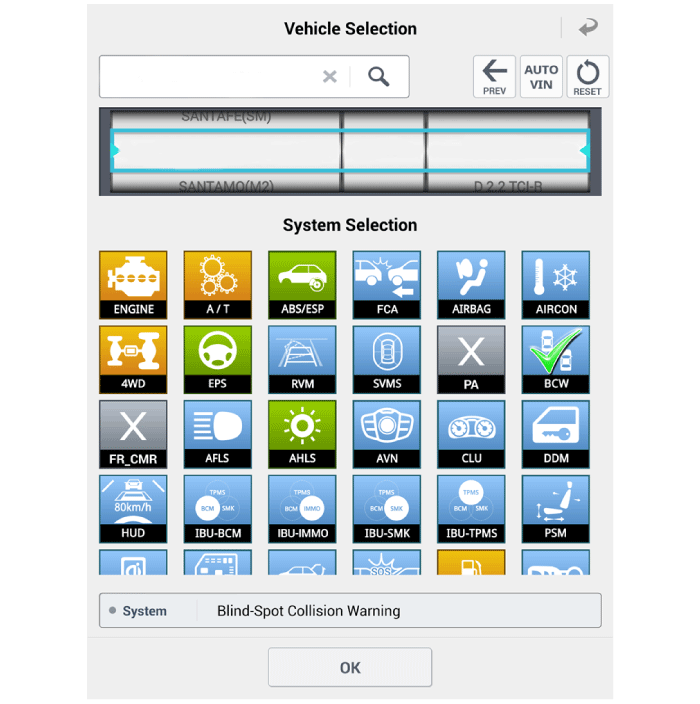
|
| 6. | If you want to check each module operation forcefully, select "Actuation test". 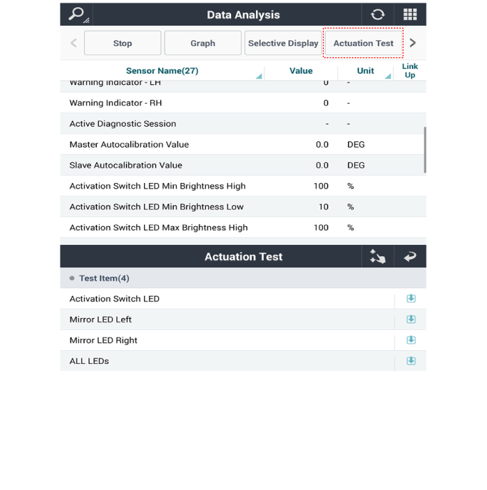
|
Components and components location
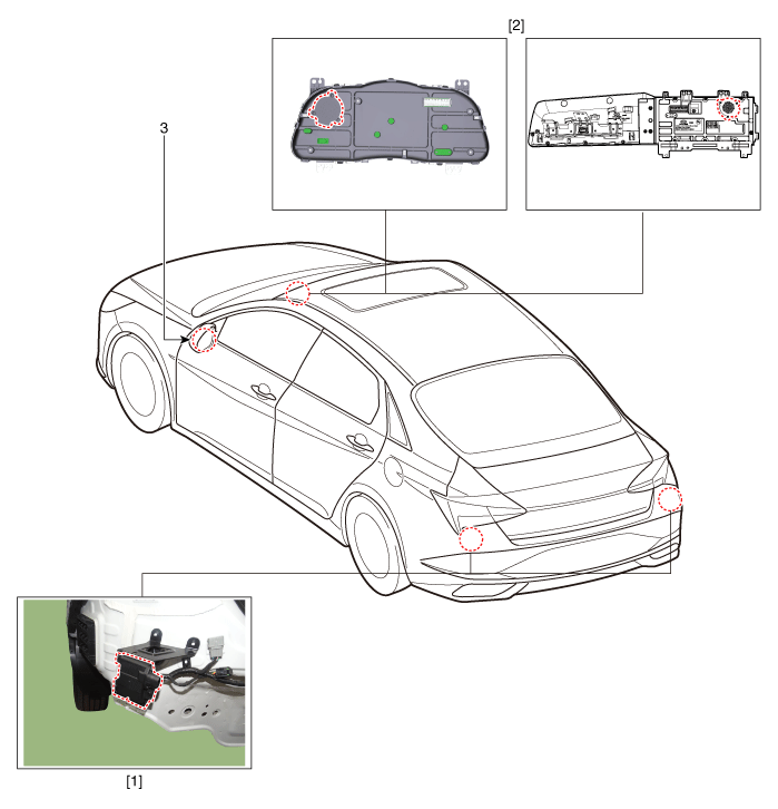
1. Rear corner radar unit
2. Speaker
| 3. Warning indicator
|
Rear Corner Radar Unit
Specifications
Items
|
Blind-Spot Collision Warning (BCW)
|
Blind-Spot Collision- Avoidance Assist-Rear (BCA-R)
|
Rated voltage
| DC 12V
|
Operating voltage
| 9V - 16V
|
Operating speed
| 30 km/h - 255 km/h
| 60 km/h - 180 km/h
|
Sensible distance
| 70m
|
Curvature radius
| Start : More than 100m
| Start : More than 625m
|
Stop : Less than 70m
| Stop : Less than 588m
|
Frequency
| 24 GHz
|
Numbers
| 2EA
|
Items
|
Rear Cross-Traffic Collision Warning (RCCW)
|
Rear Cross-Traffic Collision- Avoidance Assist (RCCA)
|
Rated voltage
| DC 12V
|
Operating voltage
| 9V - 16V
|
Operating speed
| 0 km/h - 10 km/h
| 1 km/h - 10 km/h
|
Sensible distance
| 25m
|
Curvature radius
| -
|
Frequency
| 24 GHz
|
Numbers
| 2EA
|
Items
|
Safe Exit Assist (SEA)
|
Rated voltage
| DC 12V
|
Operating voltage
| 9V - 16V
|
Operating speed
| 0 km/h - 3 km/h
|
Sensible distance
| 25m
|
Curvature radius
| -
|
Frequency
| 24GHz
|
Numbers
| 2EA
|
Schematic diagrams
| Connector and Terminal Function |
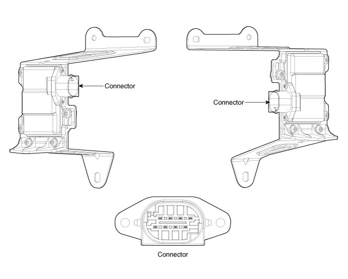
Pin
|
Function
|
1
| L-CAN High
|
2
| C-CAN High
|
3
| -
|
4
| Battery (+)
|
5
| Ground
|
6
| L-CAN Low
|
7
| C-CAN Low
|
8
| Warning indicator
|
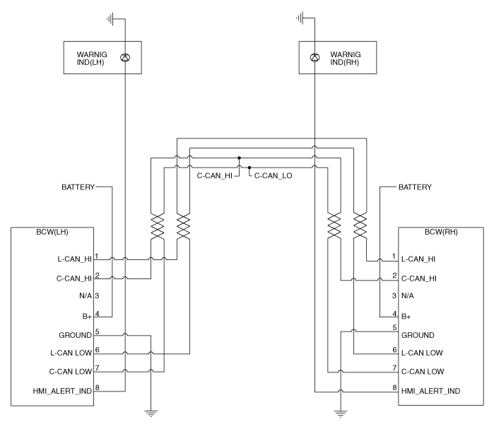
Repair procedures
lf replacement of the rear corner radar unit bracket or extension wire is required, replace the defective part only with a new one. |
| 1. | Disconnect the negative (-) battery terminal. |
| 2. | Remove the rear bumper assembly. (Refer to Body - "Rear Bumper Assembly") |
| 3. | Disconnect the rear corner radar unit connector (A). 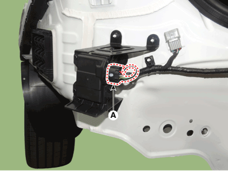
|
| 4. | Loosen the mounting screws and remove the rear corner radar lower bracket (A). 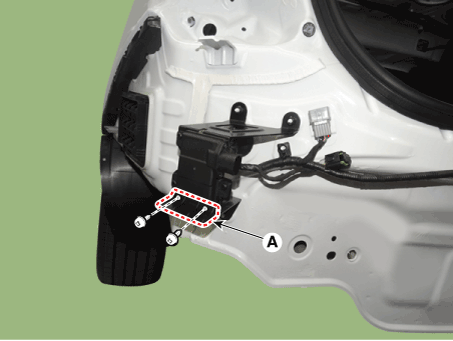
|
| 5. | Loosen the mounting screws and remove the rear corner radar unit (A). | •
| Be careful not to damage the bracket when removing the rear corner radar unit. 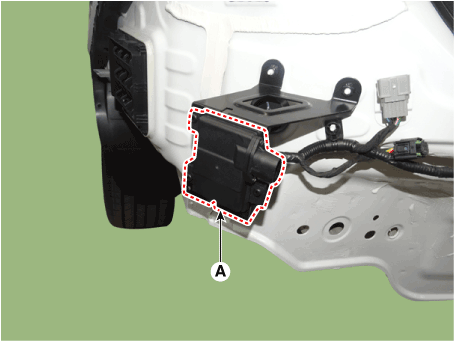
|
|
|
| 1. | Install the blind spot radar unit and bracket. Tightening torque : bracket : 3.9 - 5.9 N unit : 3.92 ± 0.105 N.m |
|
| 2. | Install the rear bumper. |
| 3. | Connect the negative (-) battery terminal. | •
| Take care not to confuse left side (master) and right side (slave) unit when installing. |
| •
| BCW units connector connect to the wiring connector. |
|
|
| 4. | Perform "Correcting the Blind-Spot Radar Unit Angle" procedures. |
| 5. | Perform "BSD Radar Calibration" procedures. |
Correcting the Blind-Spot Radar Unit Angle
| 1. | After replacing the blind-spot radar unit or bracket, with the bumper removed, use the blind-spot radar unit correction tool set (special tool : 09985-3T500) to perform angle correction. | •
| Perform the task on a level place. |
| •
| Perform the task after checking the tire pressure. |
|
| •
| For the dealer who purchased the existing blind-spot radar correction tool set (09958-3T000), refer to the instructions of the 17MY shop manual and repair it. |
|
|
| 2. | Attach a vertical plumb (special tool : 09958-3T010) on the hood, and lower the plumb (A) to the ground so that it passes through the center of the emblem. 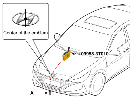
|
| 3. | Marking the center point below the plumb (A). 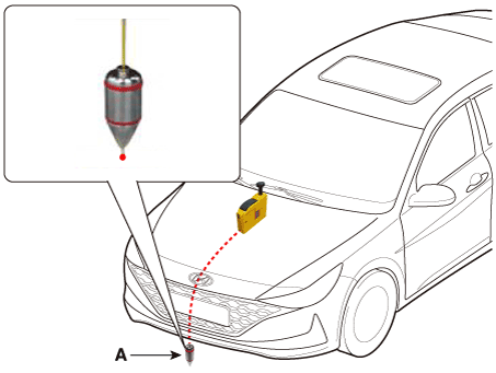
|
| 4. | Attach a vertical plumb (special tool : 09958-3T010) on the trunk (or tailgate), and lower the plumb (A) to the ground so that it passes through the center of the emblem. 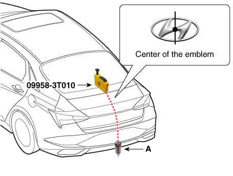
|
| 5. | Marking the center point below the plumb (A). 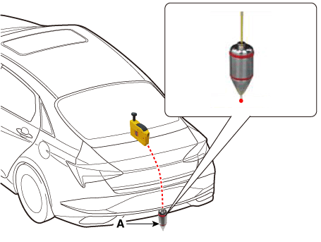
|
| 6. | Marking the center of vehicle by a string. | 1) | Pass the string through the bottom of the vehicle from the rear of the vehicle to the front and fix the string to the center point (A) of the front of the vehicle. |
| 2) | Fix the string to the point (C) about 1.5 - 2m from the back of the vehicle so that it passes the rear center point (B). |
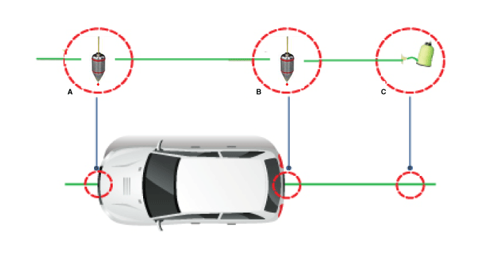
|
| 7. | Mount the blind-spot radar unit fixing adaptor (special tool : 09958-3T080) on the blind-spot radar unit and fix the level laser (special tool : 09958-3T070). 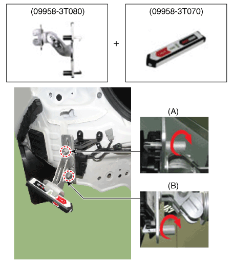
| •
| When with the blind-spot radar unit cover, remove the cover and then mount the fixing adapter (special tool: 09958-3T080). |
|
|
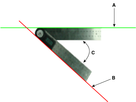
| 8. | Measure the angle (C) between the center line (A) of the angle measuring plate and the horizontal laser beam (B) using a digital protractor (special tool : 09958-3T090). Horizontal Angle (C): 44° ± 3° |
|
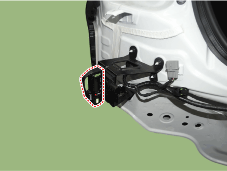
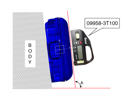
| 9. | Use a digital inclinometer (special tool : 09958-3T100) to measure the vertical angle of the blind-spot radar unit. Vertical Angle : 90° ± 1.5° |
| •
| Digital Inclinometer (09958-3T100) Vertical measurement angle (A) : 90° ± 1.5° |
|
|
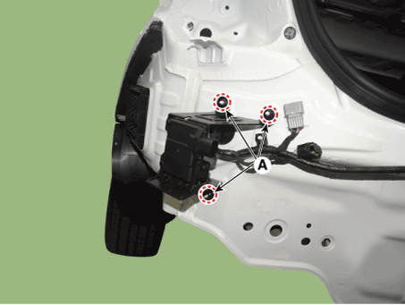
| 10. | Measure the horizontal and vertical angles of left and right blind-spot radar units. If the measured values deviate from the specified values, insert a washer between the bracket of the blind-spot radar unit. Specified Values Horizontal Angle : 44° ± 3° Vertical Angle : 90° ± 1.5° |
|
| 11. | After checking and correcting the blind-spot radar unit angle, perform the blind-spot radar radar correction procedure. |
Diagnosis with Diagnostic tool
| 1. | Rear bumper accident vehicles and vehicles that replaced BCW units must perform BCW unit alignment using Diagnostic tool. |
| 2. | Connect the cable of Diagnostic tool to the data link connector in driver side crash pad lower panel, and turn on the Diagnostic tool. |
| 3. | Select the 'S/W Management' and 'Car model'. 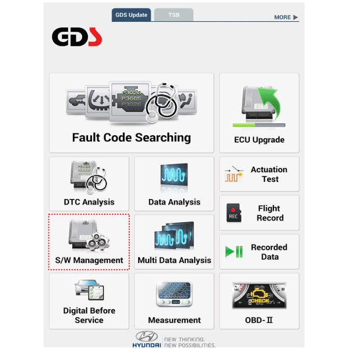
|
| 4. | Select "Blind -Spot Collision Warning" and "BSD Radar Calibration". 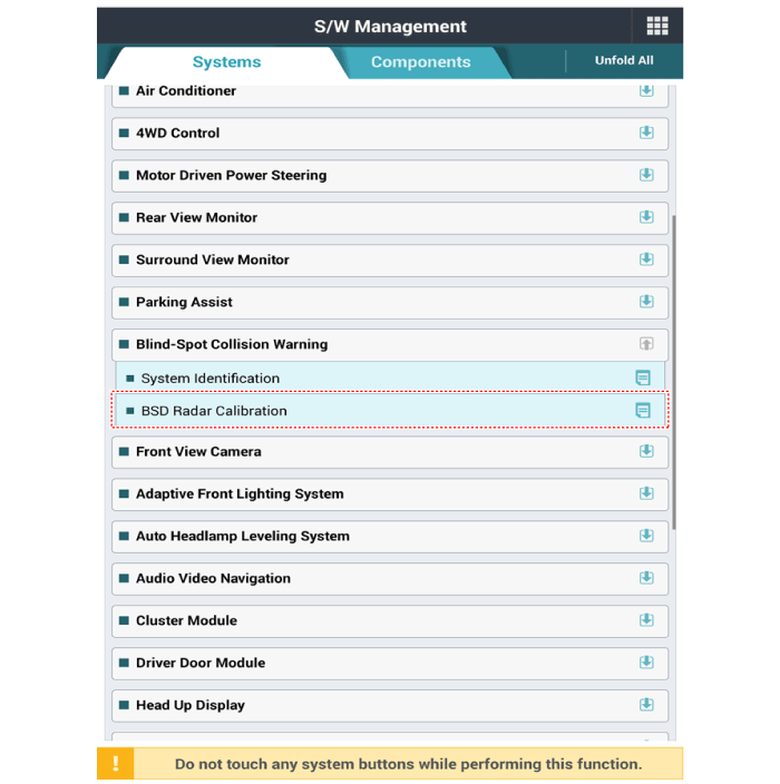
|
| 5. | Perform the "BSD Radar Calibration" procedure according to the Diagnostic tool screen message. 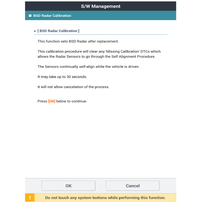
|
Warning Indicator
Components and components location
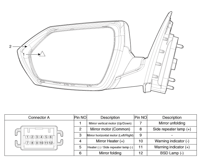
1. BSD Indicator
| 2. Side repeater lamp
|
Repair procedures
| 1. | Disconnect the negative (-) battery terminal. |
| 2. | Remove the front door trim. (Refer to Body - "Front door trim") |
| 3. | Disconnect the power door mirror connector from the harness 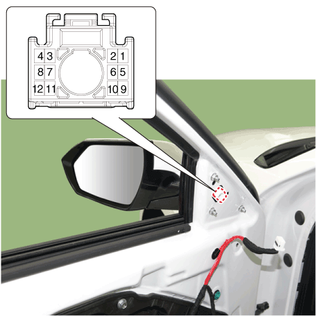
|
| 4. | Check that the mirror operates properly as shown in the below table. 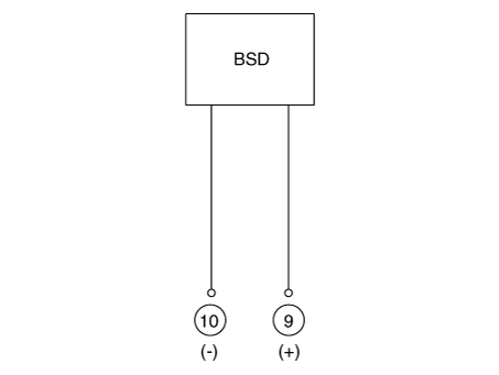
|
| 1. | Disconnect (-) battery terminal. |
| 2. | Using a fastener remover (C), remove the mirror (A) as illustration below. 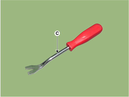
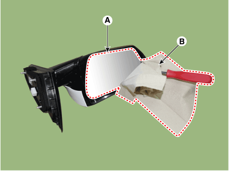
| •
| Protect mirror from removing tool with cloth (B) wrapped. |
| •
| Be careful not to damage mirror and mirror housing during removing process. |
| •
| Apply force around the center of mirror because to apply force the end of mirror will break it. |
|
|
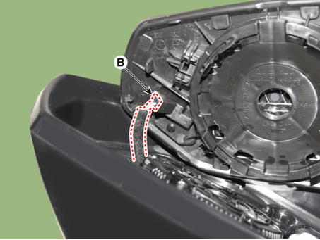
| 3. | Disconnect the mirror heat wire connectors (A) and warning indicator connector (B) and remove the mirror. 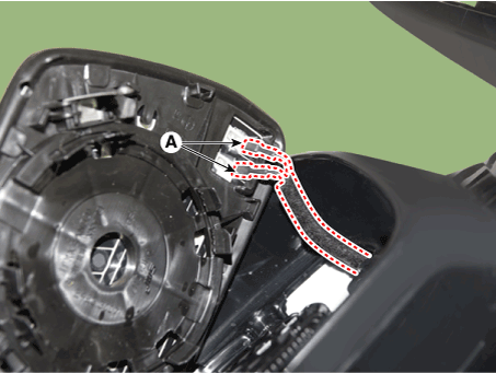
|
| 1. | Connect mirror heat wire connector and then install the mirror. |
| 2. | Connect (-) battery terminal then check if mirror works normally. |
Description and operation
DescriptionThe cruise control system is engaged by the cruise "ON/OFF" main switch located on right of steering wheel column. The system has the capability to cruise, coas ...
Description and operation
Description•
PDW consists of 8 sensors (front : 4 units, rear : 4 units) that are used to detect obstacles and transmit the result in three separate ...
 Hyundai Elantra CN7: Rear Corner Radar System


