 Hyundai Elantra CN7: Lighting System
Components and components location
| Component Location |
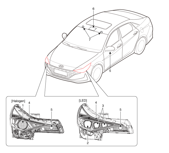
| 1. High/Low beam 2. Low beam 3. High beam 4. Position lamp&DRL | 5. Front turn signal lamp 6. Map lamp 7. Vanity lamp |
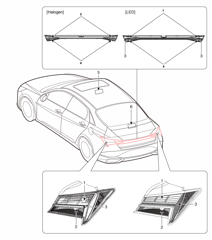
| 1. Stop lamp 2. Turn signal lamp 3. Tail lamp | 4. Back up lamp 5. Room lamp 6. High mounted stop lamp |
Specifications
| Specification |
|
Item
|
Type
|
Bulb Watt (W)
| |||
| Front | Head lamp | Halogen | Low beam / High beam | 9005L+ | 60 |
| DRL/Position lamp | LED | LED | |||
| LED | Low beam | LED | LED | ||
| High beam | LED | LED | |||
| DRL/Position lamp | LED | LED | |||
| Turn signal lamp | PY21W | 21 | |||
| Door mirror turn signal lamp | LED | LED | |||
| Rear | Rear combination | Halogen | Tail lamp | W5W | 5 |
| Tail / Stop lamp | P21/5W | 21 / 5 | |||
| Back up lamp | W 16W | 16 | |||
| Turn signal lamp | PY 21W | 21 | |||
| LED | Tail / Stop lamp | LED | LED | ||
| Back up lamp | W 16W | 16 | |||
| Turn signal lamp | PY21W | 21 | |||
| Back up lamp | PY21W | 21 | |||
| LED | LED | ||||
| License plate lamp | W5W | 5 | |||
| Interior | Map lamp | Sunroof not applied | W10W | 10 | |
| Sunroof applied | W10 | 10 | |||
| Room lamp | FESTOON | 8 | |||
| Luggage lamp | FESTOON | 5 | |||
| Vanity lamp | FESTOON | 5 | |||
Head Lamps
Repair procedures
| Head Lamp Aiming Instructions |
[Mechanical Aiming]
The head lamps should be aimed with the proper beam-setting equipment, and in accordance with the equipment manufacturer's instructions.
|
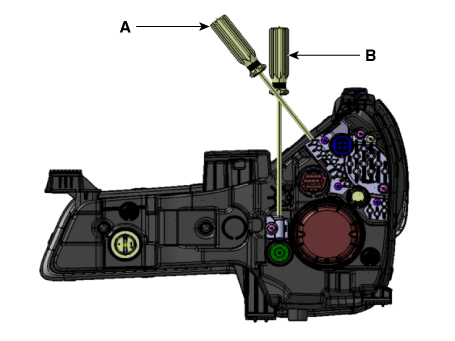
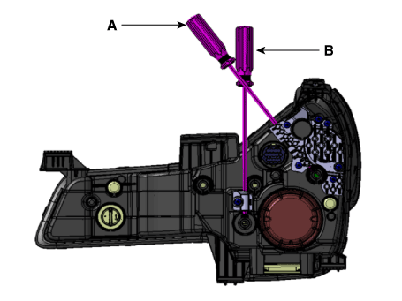
Alternately turn the adjusting gear to adjust the head lamp aiming. If beam-setting equipment is not available, proceed as follows :
| 1. | Inflate the tires to the specified pressure and remove any loads from the vehicle except the driver, spare tire, and tools. |
| 2. | The vehicle should be placed on a flat floor. |
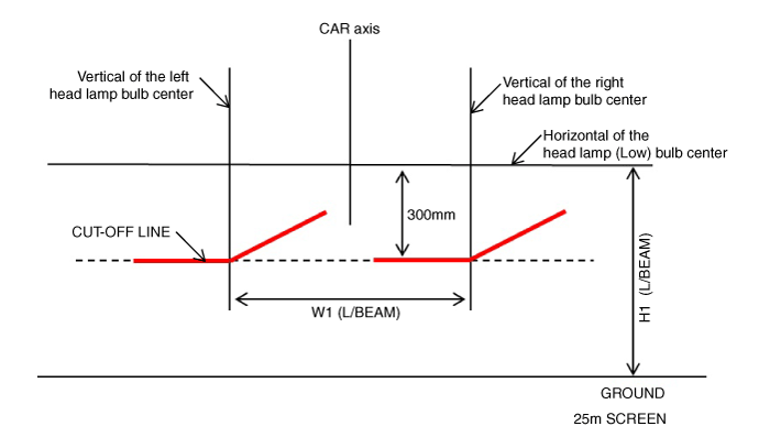
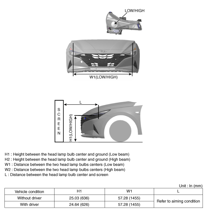
| 3. | Draw vertical lines (Vertical lines passing through respective head lamp centers) and a horizontal line (Horizontal line passing through center of head lamps) on the screen. |
| 4. | With the head lamp and battery in normal condition, aim the head lamps so the brightest portion falls on the horizontal and vertical lines.
|
[Halogen Type]
[LED Type]
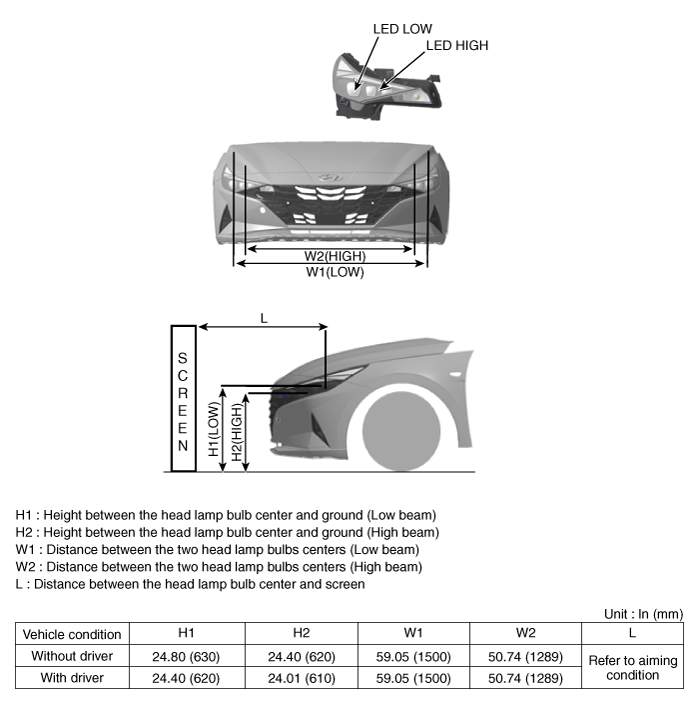
| 1. | Head Lamp (Low beam)
|
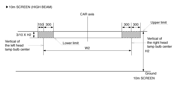
| 2. | Head Lamp (High beam) Turn the high beam on with driver seated in the vehicle. The hot zone should be projected in the allowable range shown in the picture.
|
Head Lamp Fogging
Check the below instruction procedure when the head lamp is fogged.

| Removal |
Head lamps
| 1. | Disconnect the negative (-) battery terminal. |
| 2. | Remove the front bumper cover. (Refer to Body - "Front Bumper Cover") |
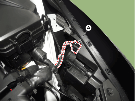
| 3. | Disconnect the head lamp connector (A).
|
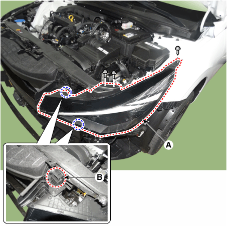
| 4. | Loosen the mounting bolts and remove the head lamp assembly (A).
|
LED Driver module
| 1. | Remove the head lamp. |
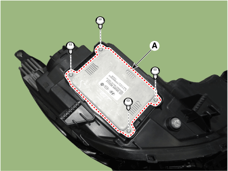
| 2. | Loosen the mounting screws and remove the LED Driver module (A).
|
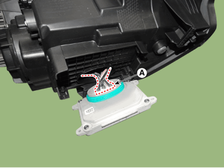
| 3. | Disconnect the LED Driver module connector (A).
|
| Installation |
Head lamps
| 1. | Install the head lamp assembly after connecting the connector. |
| 2. | Install the front bumper corver. |
| 3. | Connect the negative (-) battery terminal. |
LED Driver module
| 1. | Install the LED Driver module and connector. |
| 2. | Install the head lamp. |
| 3. | Connect the negative (-) battery terminal. |
| Replacement |
Head lamp bulb (Halogen type)
| 1. | Remove the head lamp. |
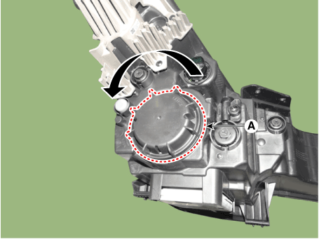
| 2. | Remove the dust cap (A) and replacement the bulb.
|
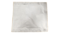
Moisture absorbent of the head lamp
|
| 1. | Remove the head lamp. |
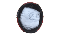
| 2. | Remove the dust cap (A) and replacement the bulb.
|
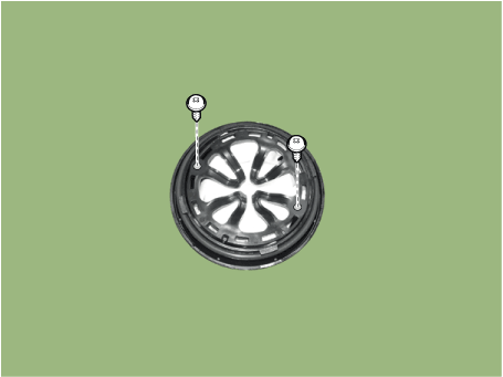
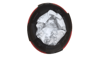
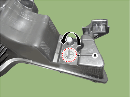
| 3. | Loosen the mounting screws and remove the moisture-absorbing agent.
|
|
Room Lamp
Repair procedures
| Removal |
[Room Lamp]
| 1. | Disconnect the negative (-) battery terminal. |
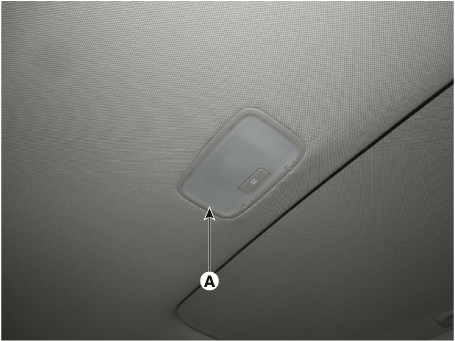
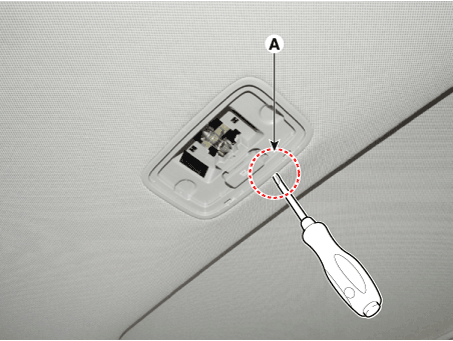
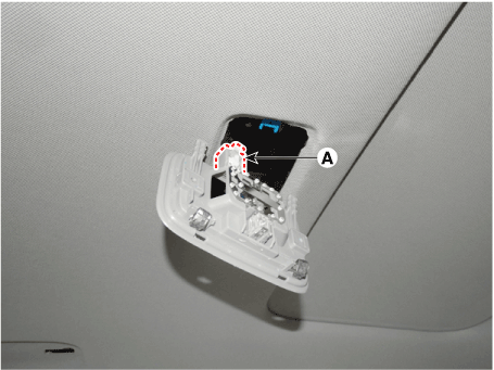
| 2. | Using a screwdriver or remover, Separate the room lamp lens (A) from the room lamp.
|
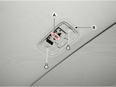
| 3. | If it is necessary to replace the bulb, remove the bulb (A) after disengaging the room lamp lens. |
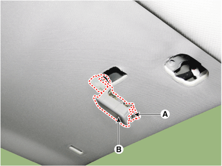
| 4. | Disengage the room lamp (B) after loosening the mounting screws.
|
| 5. | Remove the room lamp assembly after disconnect the room lamp connector.
|
[Vanity Lamp]
| 1. | Separate the vanity Lamp (A) from the roof trim after disengaging the mounting clip (B).
|
| Installation |
[Room Lamp]
| 1. | Install the room lamp after connect the connector. |
| 2. | Install the room lamp lens |
| 3. | Connect the negative (-) battery terminal. |
[Vanity Lamp]
| 1. | Install the vanity lamp. |
| 2. | Connect the negative (-) battery terminal. |
Overhead Console Lamp
Repair procedures
| Removal |
| 1. | Disconnect the negative (-) battery terminal. |
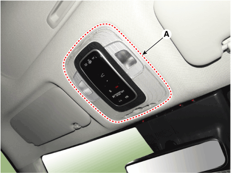
| 2. | Using a remover and remove the overhead console (A).
|
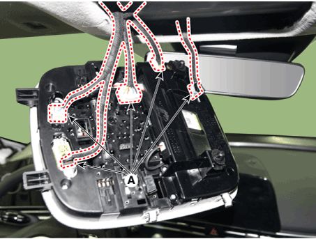
| 3. | Disconnect the overhead console connectors (A).
|
| Installation |
| 1. | Connect the overhead console connectors and install the overhead console. |
| 2. | Connect the negative (-) battery terminal. |
Hazard Lamp Switch
Repair procedures
| Removal |
| 1. | Disconnect the negative (-) battery terminal. |
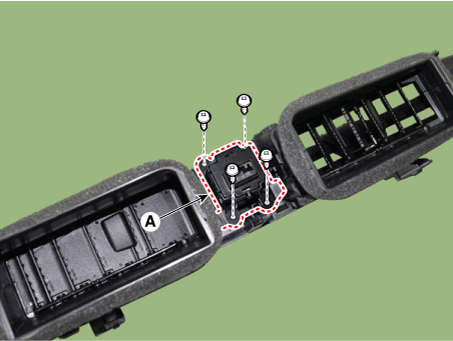
| 2. | Remove the crash pad airvent [RH]. (Refer to Body - "Crash Pad Airvent") |
| 3. | Loosen the mounting screws and remove the harzard lamp switch (A).
|
| Installation |
| 1. | To install, reverse the removal procedure. |
Rheostat
Components and components location
| Components |
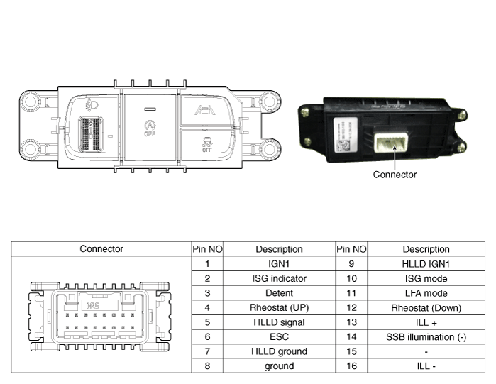
Repair procedures
| Replacement |
| 1. | Disconnect the negative (-) battery terminal. |
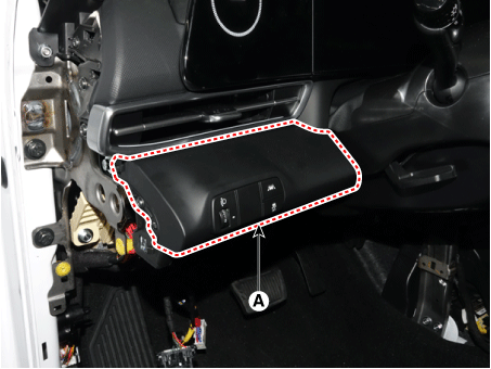
| 2. | Remove the crash pad lower panel (A). (Refer to Body - "Crash Pad Lower Panel") |
| 3. | Loosen the mounting screw and remove the crash pad lower switch (A).
|
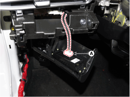
| 4. | Disconnect the crash pad lower switch connector (A).
|
| 5. | To install, reverse the removal procedure. |
Turn Signal Lamp
Repair procedures
| Removal |
| 1. | Disconnect the negative (-) battery terminal. |
| 2. | Remove the front bumper. (Refer to Body - "Front Bumper Cover") |
| 3. | Remove the head lamp. |
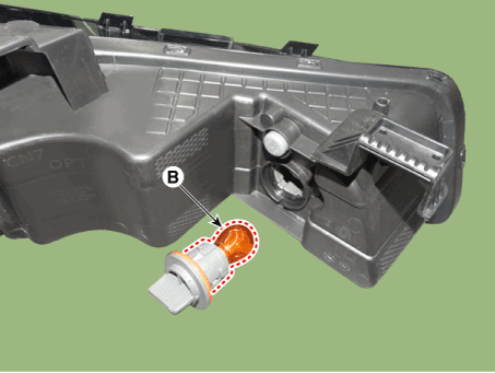
| 4. | Remove the bulb socket (A) and turn signal lamp bulb (B) from the lamp assembly.
|
| Replacement |
| 1. | Turn the head lamp power off. |
| 2. | Remove the engine room under cover. (Refer to Engine Mechanical System - "Engine Room Under Cover") |
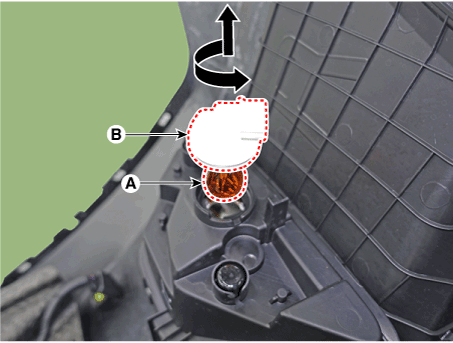
| 3. | Remove the bulb socket (B) and turn signal lamp bulb (A) from the lamp assembly.
|
| Installation |
| 1. | Install the turn siganl lamp assembly. |
| 2. | Install the head lamp. |
| 3. | Install the front bumper. |
| 4. | Connect the negative (-) battery terminal. |
License Lamps
Repair procedures
| Removal |
| 1. | Disconnect the negative (-) battery terminal. |
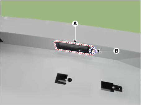
| 2. | Push the lock pin (B) and remove the license lamp (A).
|
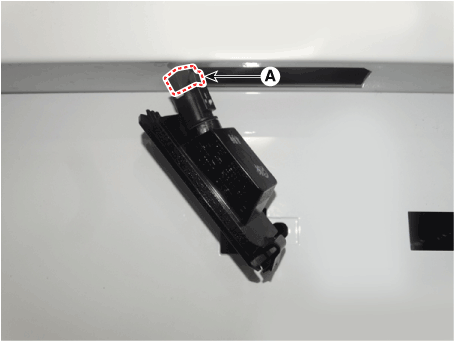
| 3. | Disconnect the license lamp connector (A).
|
| 4. | Replace the bulb (A).
|
| Installation |
| 1. | Connect the license lamp connector. |
| 2. | Install the license lamp. |
| 3. | Connect the negative (-) battery terminal. |
High Mounted Stop Lamp
Repair procedures
| Removal |
| 1. | Disconnect the negative (-) battery terminal. |
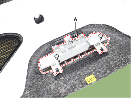
| 2. | Remove the rear package tray trim. (Refer to Body - "Rear Package Tray Trim") |
| 3. | Loosen the mounting screws and remove the high mounted stop lamp (A).
|
| Installation |
| 1. | Install the high mounted stop lamp. |
| 2. | Install the rear package tray trim. |
| 3. | Connect the negative (-) battery terminal. |
Rear Combination Lamp
Repair procedures
| Removal |
Outside Combination Lamp
| 1. | Disconnect the negative (-) battery terminal. |
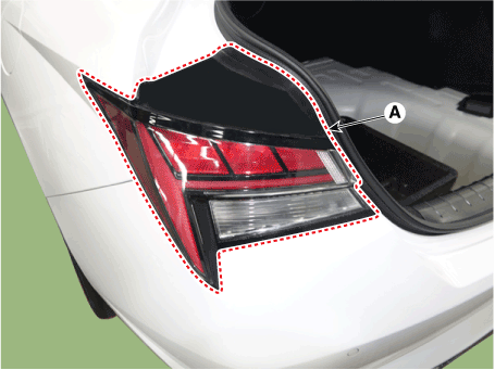
| 2. | Remove the combination lamp cover (A).
|
| 3. | Disconnect the rear combination lamp connector (A).
|
| 4. | Loosen the mounting nuts and remove the rear conbination lamp (A).
|
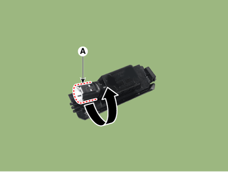
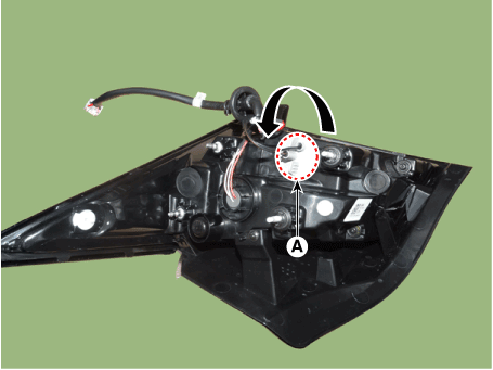
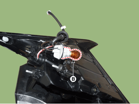
| 5. | Remove the socket (A) and replace the bulb (B).
|
Inside Combination Lamp
| 1. | Disconnect the negative (-) battery terminal. |
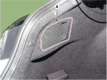
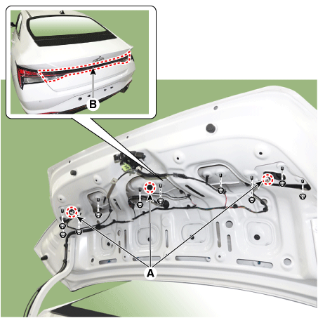
| 2. | Remove the trunk lid trim. (Refer to Body - "Trunk Lid Trim") |
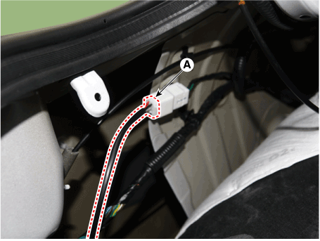
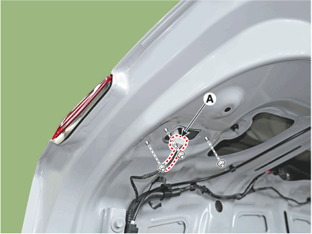
| 3. | Disconnect the rear inside combination lamp connectors and trunk lid button connector (A). |
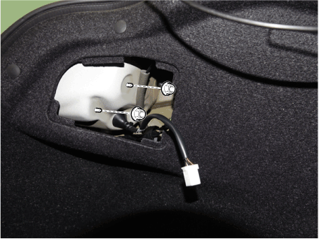
| 4. | Loosen the mounting nuts and remove the rear inside combination lamp (B).
|
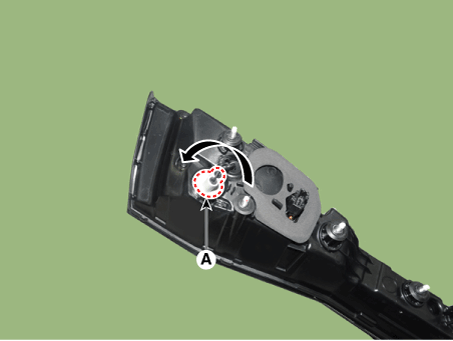
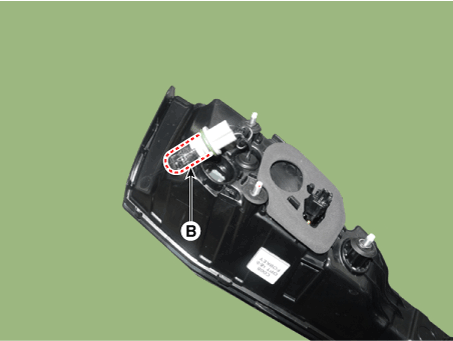
| 5. | Remove the rear inside combination lamp sockec [back-up lamp] (A) and replace the bulb (B).
|
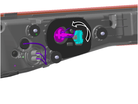
| 6. | Remove the rear inside combination lamp sockec [tail lamp] (A) and replace the bulb (B).
|
| Replacement |
Outside Combination Lamp
| 1. | Turn the head lamp power off. |
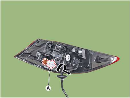
| 2. | Remove the bulb socket and turn signal lamp bulb (A) from the lamp assembly.
|
Inside Combination Lamp
| 1. | Turn the head lamp power off. |
| 2. | Remove the trunk lid trim. (Refer to Body - "Trunk Lid Trim") |
| 3. | Remove the bulb socket and turn signal lamp bulb (A) from the lamp assembly.
|
| Installation |
| 1. | Connecting the lamp connector. |
| 2. | Install the inside/outside rear combination lamp assembly. |
| 3. | Install the trunk lid trim. [Inside combination lamp only] |
Mood Lamp
Repair procedures
| Removal |
Mood lamp unit
| 1. | Disconnect the negative (-) battery terminal. |
| 2. | Remove the main crash pad assembly. (Refer to Body - "Main Crash Pad Assembly") |
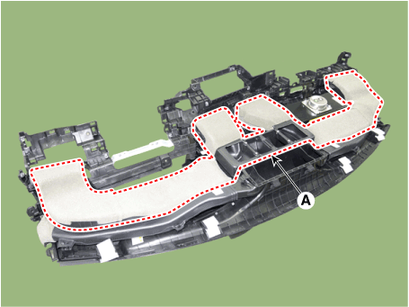
| 3. | Loosen the mounting screws and remove the main crash pad air duct (A).
|
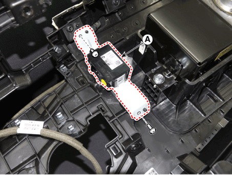
| 4. | Loosen the mounting screws and remove the mood lamp unit (A).
|
Crash pad mood lamp [LH]
| 1. | Disconnect the negative (-) battery terminal. |
| 2. | Remove the crash pad lower panel. (Refer to Body - "Crash Pad Lower Panel") |
| 3. | Loosen the mounting screws and remove the crash pad lower switch (A).
|
| 4. | Disconnect the crash pad lower switch connector (A).
|
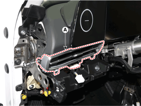
| 5. | Loosen the mounting screw and remove the crash pad air vent [LH]
|
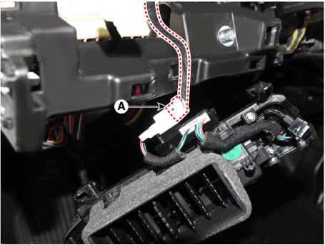
| 6. | Disconnect the mood lamp connector (A).
|
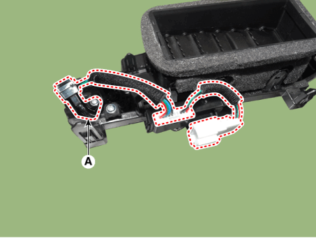
| 7. | Loosen the mounting screw and connector and remove the crash pad mood lamp [LH] (A).
|
Crash pad mood lamp [RH]
| 1. | Disconnect the negative (-) battery terminal. |
| 2. | Remove the crash pad air vent [RH]. (Refer to Body - "Crash Pad Air Vent") |
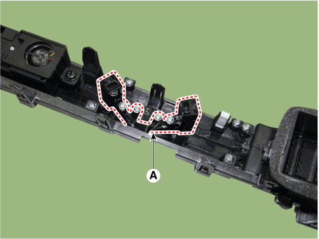
| 3. | Loosen the mounting screws and remove the crash pad mood lamp [RH] (A).
|
| Installation |
| 1. | To install, reverse the removal procedure. |


