Removal and Installation
| 1. |
Remove the engine cover.
|
| 2. |
Disconnect the battery negative terminal.
Tightening torque:
4.0 ~ 6.0 N.m (0.4 ~ 0.6 kgf.m, 3.0 ~ 4.4 lb-ft)
|
|
| 3. |
Disconnect the wiring connectors and harness clamps, and then
remove the wiring and protectors from the intake manifold.
| (1) |
The intake OCV (Oil control valve) connector (A)

|
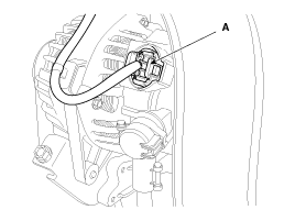
| (2) |
The alternator connector (A)

|
| (3) |
The VIS (Variable Intake System) connector (A)

|
| (4) |
The MAPS (Manifold absolute pressure sensor) & IATS (Intake
air temperature sensor) connector (A)

|
| (5) |
The ETC (Electronic throttle control) connector (A)

|
| (6) |
The VCMA (Variable charge motion actuator) connector (A)

|
|
| 4. |
Disconnect the PCV (Positive crankcase ventilation) hose (A).

|
| 5. |
Disconnect the vacuum hose (A) and PCSV (Purge control solenoid
valve) hose (B).

|
| 6. |
Unfasten the ETC (Electric throttle body control) module bolts
(A). (Refer to FL – “ETC system”)
Tightening torque:
9.8 ~ 11.8 N.m (1.0 ~ 1.2 kgf.m, 7.2 ~ 8.7 lb-ft)
|

|
| 7. |
Remove the intake manifold stay (A).
Tightening torque:
18.6 ~ 23.5 N.m (1.9 ~ 2.4 kgf.m, 13.7 ~ 17.4 lb-ft)
|

|
| 8. |
Remove the intake manifold (A) with the gasket (B).
Tightening torque:
18.6 ~ 23.5 N.m (1.9 ~ 2.4 kgf.m, 13.7 ~ 17.4 lb-ft)
|

|
When installing the intake manifold, tighten the bolts
and nuts with pre-torque first, and then tighten the bolts and
nuts with specified torque in the sequence shown.
|

|
| 9. |
Installation is reverse order of removal.
|
When installing, replace with new gaskets.
|
|
Components
1. Intake
manifold assembly
2. Intake manifold gasket
3. Electronic
throttle body
4. Intake manifold stay
...
Components
[ULEV]
1. Heat
protector
2. Exhaust manifold gasket
3. Exhaust
manifold
4. Exhaust manifold stay
[SLUEV]
...
 Hyundai Elantra MD/UD: Intake Manifold. Repair procedures


