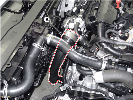
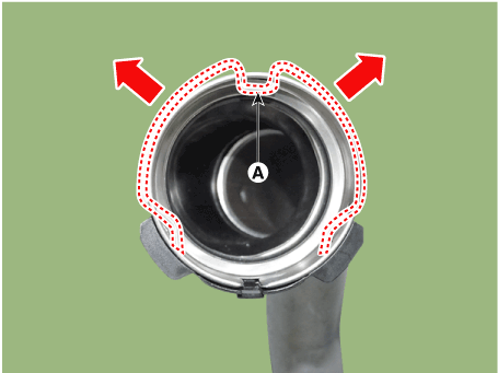
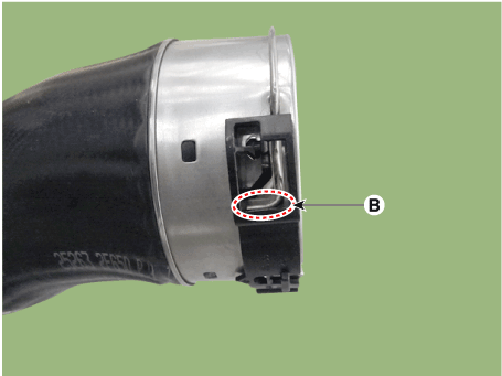
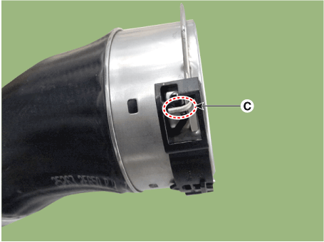
 Hyundai Elantra CN7: Intake And Exhaust System
Air Cleaner
Components and components location
| Components |
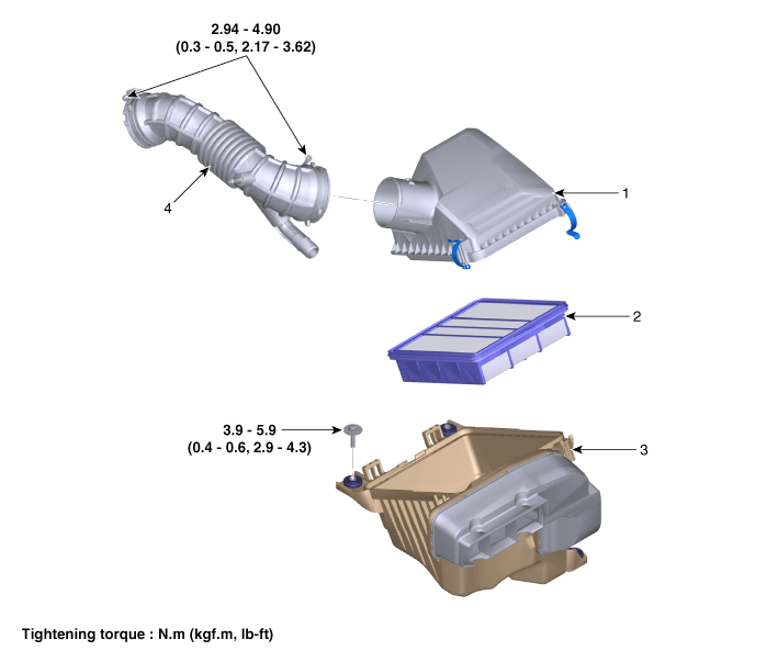
| 1. Air cleaner cover 2. Air cleaner element | 3. Air cleaner body & air duct 5. Air intake hose |
Repair procedures
| Removal and Installation |
Air Cleaner Assembly.
| 1. | Disconnect the battery negative terminal. |
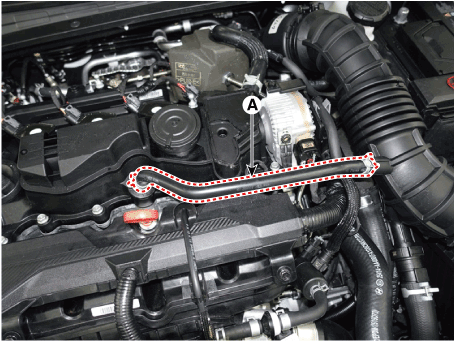
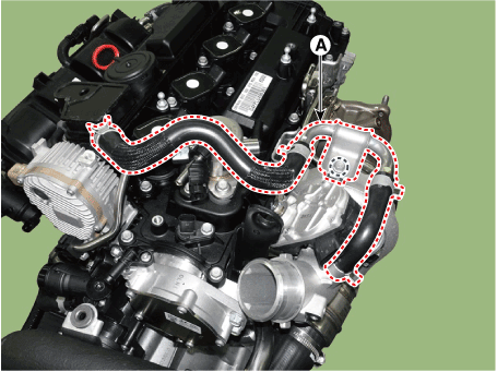
| 2. | Disconnect the breather hose (A).
|
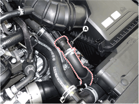
| 3. | Disconnect the RCV hose (A).
|
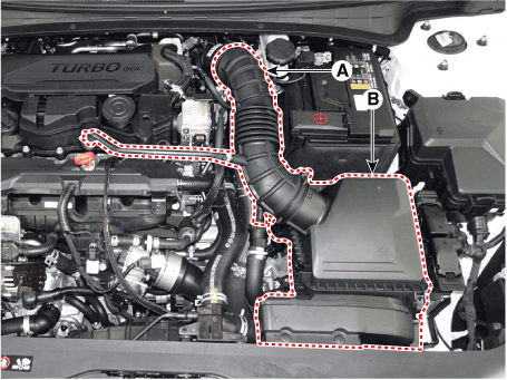
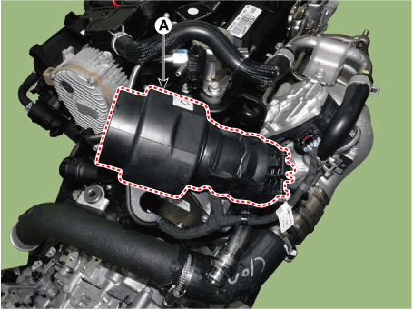
| 4. | Disconnect the air intake hose (A), and then remove the air cleaner assembly (B).
|
| 5. | Install in the reverse order of removal. |
Air Cleaner Element Replacement
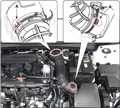
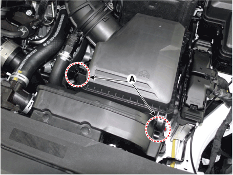
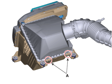
| 1. | Open the air cleaner cover by unhooking the clamps (A).
|
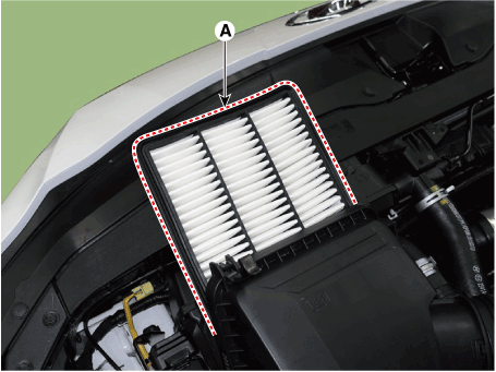
| 2. | Replace the air cleaner element (A) with a new one.
|
| 3. | Close the air cleaner cover by hooking the clamps.
|
Intake Manifold
Components and components location
| Components |
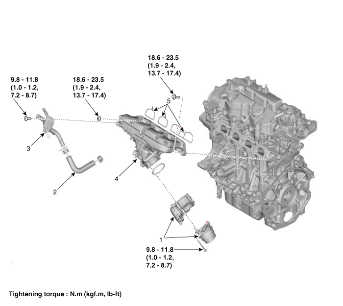
| 1. Electronic throttle body (ETC) 2. Return hose 3. Return pipe | 4. Intake manifold 5. Intake manifold gasket |
Repair procedures
| Removal and Installation |
| 1. | Disconnect the battery negative terminal. |
| 2. | Remove the engine cover. (Refer to Engine and Transaxle Assembly - "Engine Cover") |
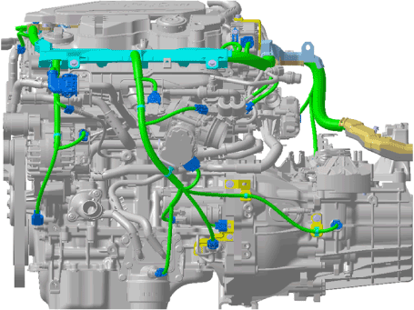
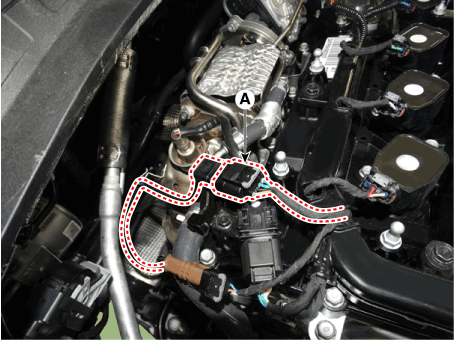
| 3. | Remove the engine wire harness connectors and wire harness clamps from cylinder head and the intake manifold.
|
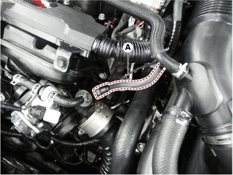
| 4. | Disconnect the intercooler outlet hose (A).
|
| 5. | Remove the purge control solenoid valve (PCSV) hose (A).
|
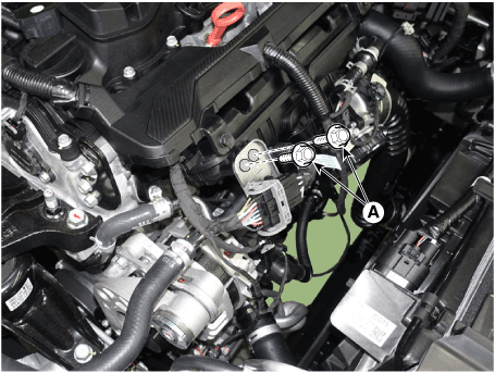
| 6. | Remove the water return hose & pipe bracket bolts (A).
|
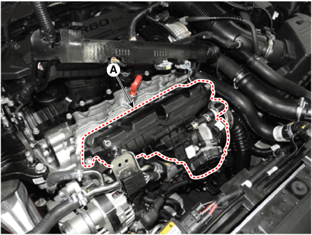
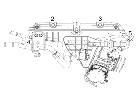
| 7. | Remove the Intake Manifold (A).
|
| 8. | Install in the reverse order of removal. |
Exhaust Manifold
Components and components location
| Components |
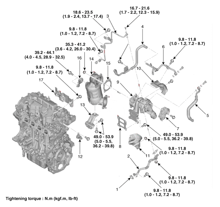
| 1. Oil drain pipe gasket 2. Oil drain pipe 3. Oil feed pipe 4. Torbo charhe water outlet hose & pipe B 5. Torbo charhe water inlet pipe 6. Torbo charhe water outlet pipe A 7. Electric waste gate actuator (EWGA) 8. Exhaust manifold gasket 9. Exhaust manifold & Turbo charger | 10. Exhaust manifold heat protector A 11. Exhaust manifold heat protector B 12. Intercooler pipe braket 13. Exhaust manifold & Turbo charger stay bracket 14. Warm up catalytic converter 15. Warm up catalytic converter gasket 16. Warm up catalytic converter upper stay bracket 17. Cylinder head heat peotector |
Repair procedures
| Removal and Installation |
| 1. | Disconnect the negative battery terminal. |
| 2. | Remove the engine cover. (Refer to Engine and Transaxle Assembly - "Engine Cover") |
| 3. | Remove the engine room under cover. (Refer to Engine and Transaxle Assembly - "Engine Room Under Cover") |
| 4. | Drain the coolant. (Refer to Cooling System - "Coolant") |
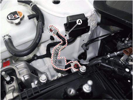
| 5. | Disconnect the engine ground cable (A).
|
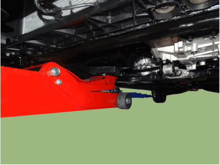
| 6. | Install the jack to the edge of oil pan.
|
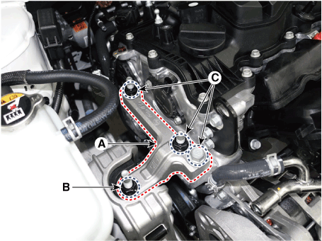
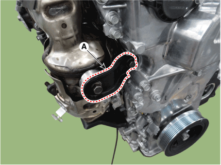
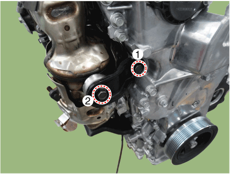
| 7. | Remove the engine mounting support bracket (A).
|
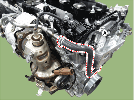
| 8. | Disconnect the turbo charger outlet hose (A).
|
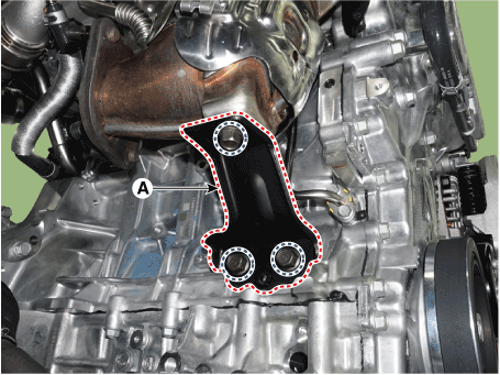
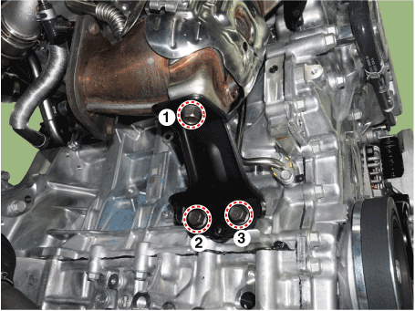
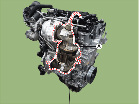
| 9. | Remove the warm up catalytic converter(WCC) upper stay bracket (A).
|
| 10. | Remove the front muffler. (Refer to Intake and Exhaust Manifold - "Front Muffler") |
| 11. | Remove the warm up catalytic converter(WCC) lower stay bracket (A).
|
| 12. | Remove the warm up catalytic converter (WCC) (A).
|
| 13. | Remove the air duct and air cleaner assembly. (Refer to Intake and Exhaust System - "Air Cleaner") |
| 14. | Remove the battery and battery tray. (Refer to Engine Electrical System - "Battery") |
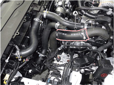
| 15. | Disconnect the turbo charger intake hoseB (A).
|
| 16. | Remove the tbreather hose and pipe (A).
|
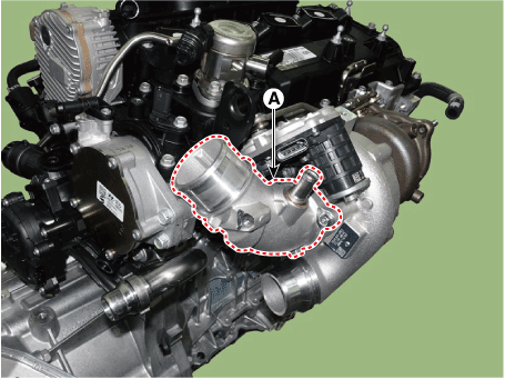
| 17. | Remove the turbo charger inlet pipe (A).
|
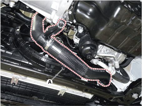
| 18. | Disconnect the intercooler inlet hose (A).
|
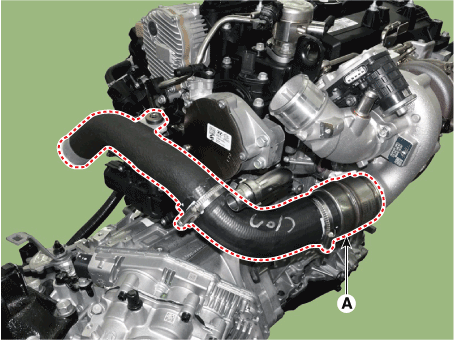
| 19. | Remove the intercooler hose & pipe (A).
|
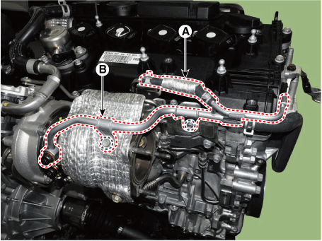
| 20. | Disconnect the turbo charger outlet hose (A), and then remove the water pipe (B).
|
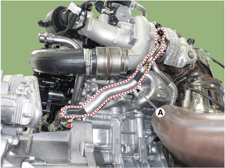
| 21. | Remove the turbo charger inlet hose & pipe (A).
|
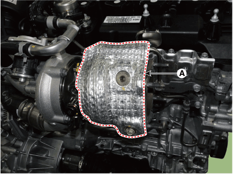
| 22. | Remove the turbo charger heat protect (A).
|
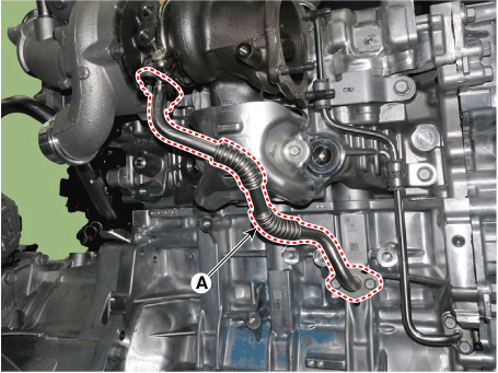
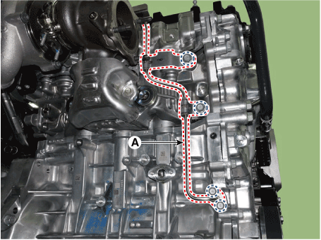
| 23. | Remove the turbo charger oil drain pipe(A).
|
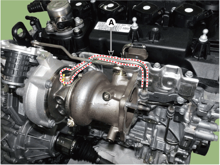
| 24. | Remove the turbo charger oil feed pipe(A).
|
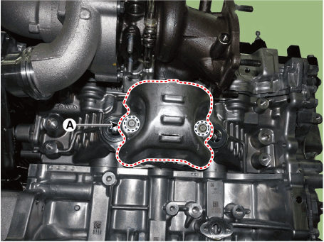
| 25. | Remove the turbo charger heat protector (A).
|
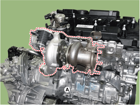
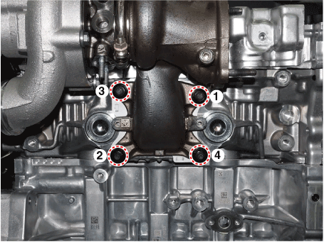
| 26. | Remove the exhaust manifold & turbo charger (A).
|
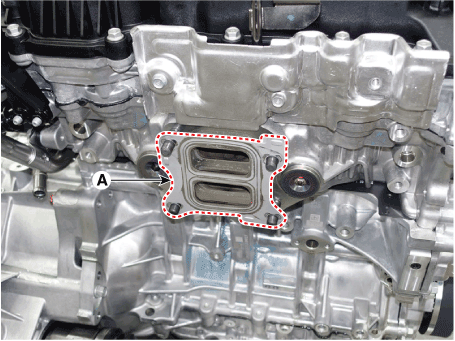
| 27. | Remove the exhaust manifold & turbo charger gasket (A).
|
| 28. | Remove the C- ring, and then remove the electric WGT control actuator (A) after loosening the mounting bolts.
|
| 29. | Install in the reverse order of removal.
|
Turbo Charger
Repair procedures
| Removal and Installation |
| 1. | Remove the Turbocharger & Exhaust Manifold. (Intake And Exhaust System - "Exhaust Manifold") |
| On-vehicle Inspection |
| Turbocharger Diagnostic Flow |
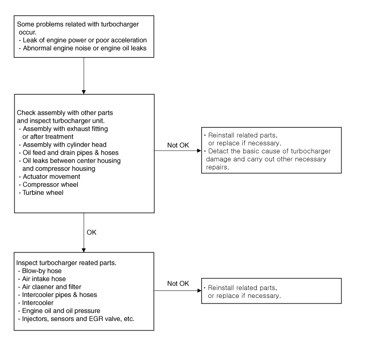
If any problem related with turbocharger, such as lack of engine power, poor acceleration, abnormal engine noise or oil leaks, may occur, check the turbocharger according to the procedure as follows.
| 1. | Check the assembly of the turbocharger and the exhaust fitting (or the after treatment).
Gas leakage caused by lack of gasket or inadequately tightened mounting bolts (or nuts) may cause abnormal engine noise. If the cause of the problem is detected, retighten the mounting bolts (or nuts) to the specified torque or replace the gasket or damaged parts with new ones if necessary. |
| 2. | Check the assembly of the exhaust manifold and the cylinder head.
Gas leakage caused by lack of gasket or inadequately tightened mounting bolts (or nuts) may cause abnormal engine noise. If the cause of the problem is detected, retighten the mounting bolts (or nuts) to the specified torque or install a new gasket if necessary. |
| 3. | Check the turbocharger oil feed pipe & hose and oil drain pipe & hose.
If a gas leak occur as a gasket was not installed or mounting bolts were tightened inadequately, it may cause oil leaks. If the oil feed pipe & hose is damaged, engine oil is not supplied sufficiently to the turbocharger then it may damage the turbocharger. If the oil drain pipe & hose is damaged and clogged, engine oil is not drained smoothly then it may cause oil leaks from the turbocharger. If the cause of the problem is detected, retighten the mounting bolts (or nuts) to the specified torque or replace the gasket or damaged parts with new ones if necessary. |
| 4. | Check for oil leakage between center housing and compressor housing.
Damaged O-ring (gasket) between the center housing and the compressor housing may cause oil leakage. If an oil leak is detected, replace the turbocharger with a new one. |
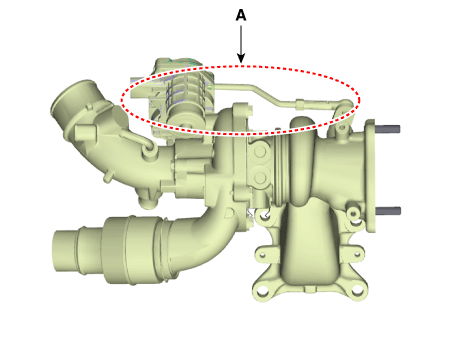
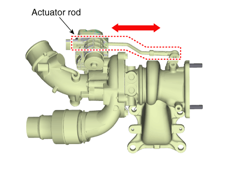
| 5. | Inspect the rod unit of the electric waste gate actuator (EWGA).
Damaged turbocharger actuator may cause lack of engine power and poor acceleration. If the actuator rod does not move, replace the turbocharger with a new one. |
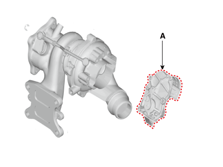
| 6. | Check the electric waste gate actuator (EWGA).
|
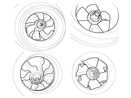
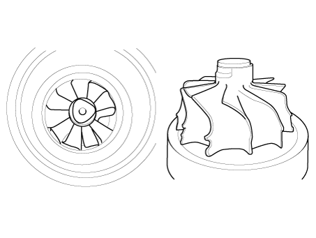
| 7. | Check the turbocharger compressor wheel.
Damaged compressor wheel may cause abnormal noise from the turbocharger and poor acceleration. If the compressor wheel are damaged or deformed, replace the turbocharger with a new one. |
| 8. | Check the turbocharger turbine wheel.
Damaged turbine wheel may cause abnormal noise from the turbocharger and poor acceleration. If the turbine wheel are damaged or deformed, replace the turbocharger with a new one. |
If no problem is detected from the turbocharger, check the turbocharger-related parts according to the procedure as follows.
| 9. | Check the blow-by hose. (Refer to FL group)
If the breather hose is bent or clogged, the internal pressure in the engine will increase and engine oil will not be supplied smoothly to the turbocharger, causing damage to the turbocharger and oil leakage. If the cause of the problem is detected, replace the breather hose or the related parts with new ones. |
| 10. | Check the air intake hose connected to the turbocharger.
If the cross-section of the hose diminishes as the air intake hose is bent or crushed, intake air to the turbocharger will be reduced and the pressure in front of turbocharger will drop, causing damage to the turbocharger or oil leakage. If the air intake hose is detached or torn, foreign substances may go into the turbocharger causing damage to it. If the air intake hose is damaged, replace it with a new one. |
| 11. | Check the air cleaner.
If the air cleaner filter is moistened or polluted excessively or a non-genuine part is used, intake air to the turbocharger will be reduced and the pressure in front of turbocharger will drop, causing damage to the turbocharger and oil leakage. If the air cleaner filter is moistened or polluted excessively, replace it with a new one.
|
| 12. | Check the intercooler hoses & pipes.
If the intercooler hoses & pipes are damaged or disconnected, oil leakage may occur from the hoses & pipes and the turbocharger may exceed the permissible speed causing damage to the turbocharger. If the intercooler hoses & pipes are damaged, replace them with new ones.
|
| 13. | Check the intercooler.
If the intercooler is damaged, the turbocharger may exceed the permissible speed causing damage to the turbocharger. If the intercooler is damaged, replace them with a new one.
|
| 14. | Check the engine oil.
If the engine oil level is low, amount of engine oil fed to turbocharger will be reduced causing the bearings in the turbocharger to adhere due to insufficient lubrication and cooling. If the cause of the problem is detected, add or change engine oil.
|
| 15. | Check the engine oil pressure.
If the engine oil level is low, amount of engine oil fed to turbocharger will be reduced causing the bearings in the turbocharger to adhere due to insufficient lubrication and cooling. If the cause of the problem is detected, add or change engine oil. If foreign substances are accumulated on the oil screen, wash the oil screen and replace the injector’s washer with a new one after checking the injectors for gas leaks. Check the engine oil-related parts, such as oil pump, if necessary.
|
| 16. | Check the injectors, sensors, etc. (Refer to Engine Control / Fuel System)
Improper operation of the injectors, sensors, EGR valve, etc. may cause diminished engine power. If the cause of the problem is detected, replace the related parts with new ones. |
Intercooler
Repair procedures
| Removal and Installation |
| 1. | Disconnect the battery negative terminal. |
| 2. | Remove the engine room under cover. (Refer to Engine and Transaxle Assembly - "Engine Room Under Cover") |
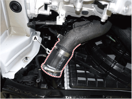
| 3. | Disconnect the intercooler inlet hose (A).
|
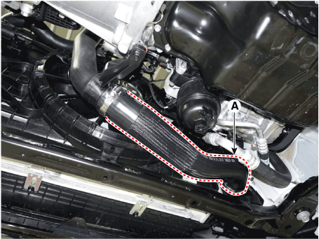
| 4. | Disconnect the intercooler outlet hose (A).
|
| 5. | Remove the front bumper cover. (Refer to Body - "Front Bumper Cover") |
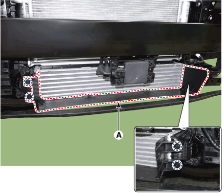
| 6. | Remove the intercooler air guard (A).
|
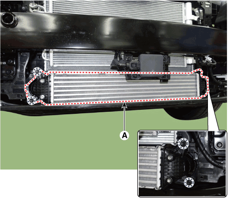
| 7. | Remove the intercooler (A).
|
| 8. | Install in the reverse order of removal. |
Intercooler inlet pipe
| 1. | Disconnect the battery negative terminal. |
| 2. | Remove the air duct and air cleaner assembly. (Refer to Intake and Exhaust System - "Air Cleaner") |
| 3. | Remove the battery and battery tray. (Refer to Engine Electrical System - "Battery") |
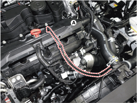
| 4. | Remove the intercooler inlet hose and pipe.
|
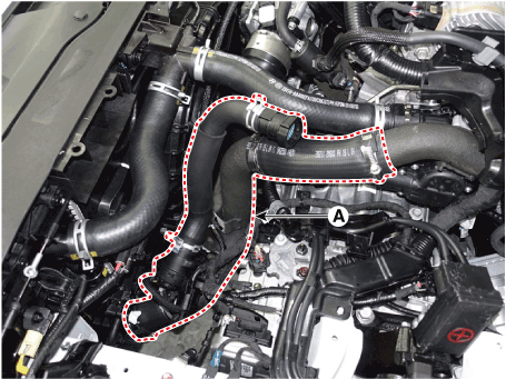
| 5. | Remove the intercooler hose & pipe (A).
|
| 6. | Install in the reverse order of removal. |
Intercooler outlet pipe
| 1. | Disconnect the battery negative terminal. |
| 2. | Remove the engine room under cover. (Refer to Engine and Transaxle Assembly - "Engine Room Under Cover") |
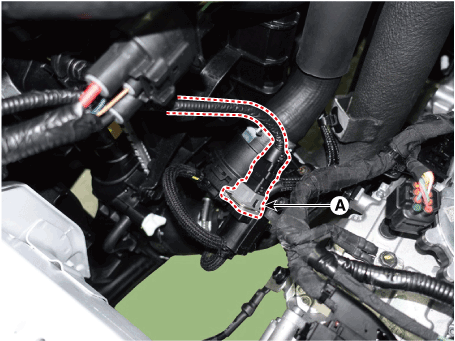
| 3. | Remove the intercooler outlet hose and pipe.
|
| 4. | Install in the reverse order of removal. |
Muffler
Components and components location
| Components |
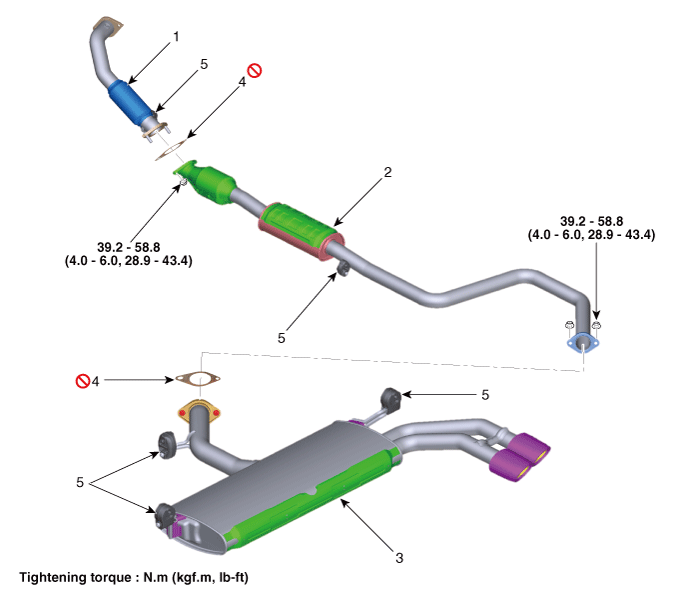
| 1. Front muffler 2. Catalytic converter & Center muffler 3. Rear muffler | 4. Gasket 5. Hanger |
Repair procedures
| Removal and Installation |
Front Muffler
| 1. | Disconnect the battery negative terminal. |
| 2. | Disconnect the oxygen sensor connector (A).
|
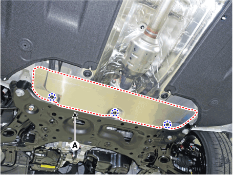
| 3. | Remove the heat protector (A).
|
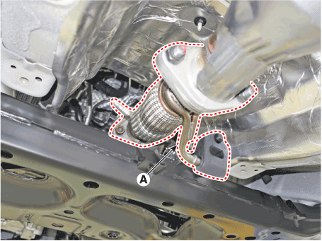
| 4. | Remove the front muffler (A) after disconnecting the hanger.
|
| 5. | Install in the reverse order of removal.
|
Catalytic Converter & Center Muffler
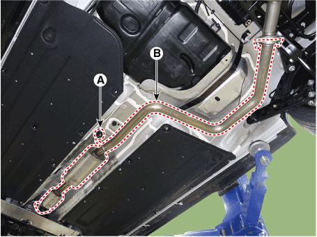
| 1. | Remove the catalytic converter & center muffler.
|
| 2. | Install in the reverse order of removal.
|
Rear Muffler
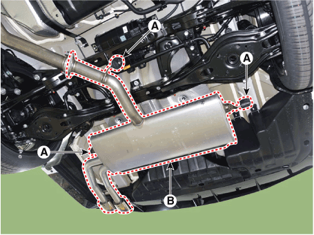
| 1. | Remove the rear muffler.
|
| 2. | Install in the reverse order of removal.
|
Replacement procedure of center muffler using clamp
Under warranty : Replace the center muffler assembly.
Out of warranty : It is available to replace the center muffler as the procedure below.
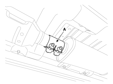
| 1. | Check that the clamping part of the center muffler assembly is damaged or deformed. If the muffler is too corroded to clamp, replace the center muffler assembly.
|
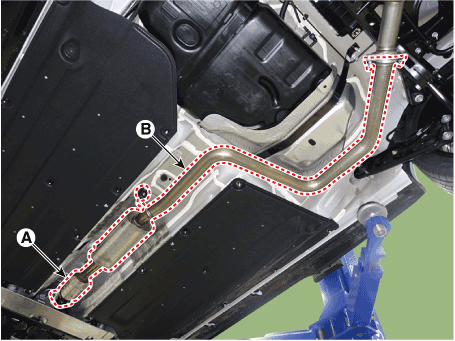
| 2. | Remove the catalytic converter & center muffler.
|
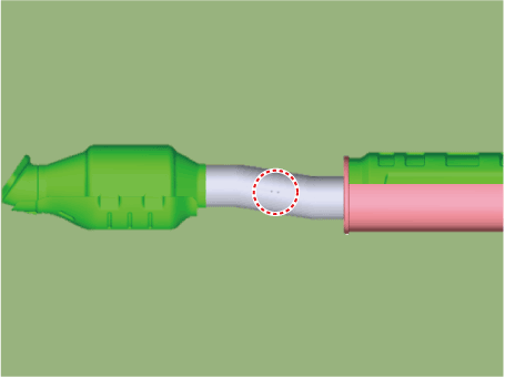
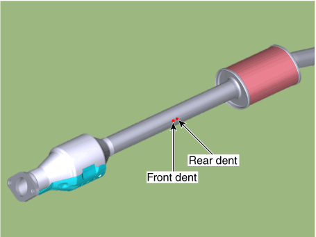
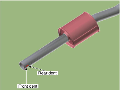
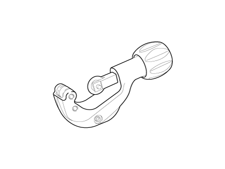
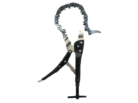
| 3. | Cut the center muffler as the instruction below.
[A/S muffler]
|
| 4. | Install the center muffler.
|

