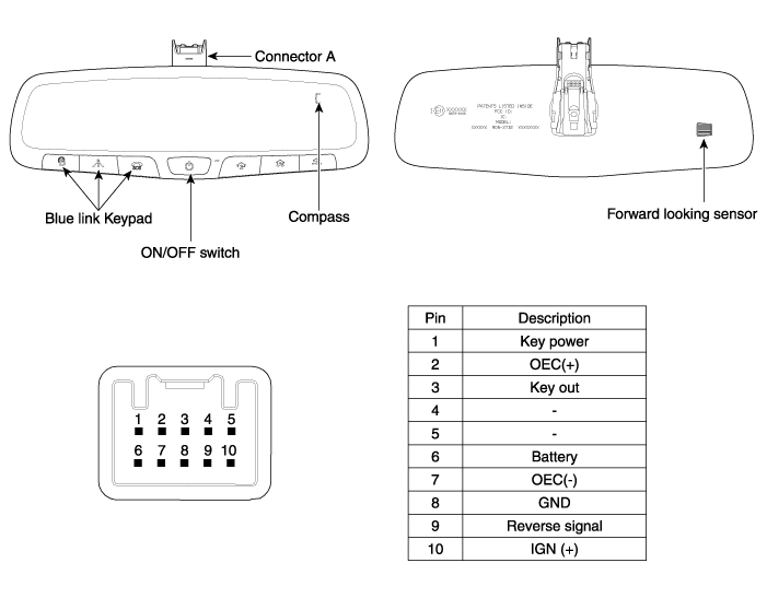
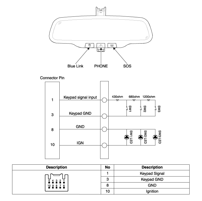
Components and Components Location


Description and Operation
The ECM (Electro Chromatic inside rear view Mirror) is intended dim the reflecting
light in the rear view mirror. The forward facing sensor detects brightness of the
surroundings, while the rearward looking sensor is for the light from the rear.
The strength of the light in the rear sensor is used by the mirror to adjust the
shading. It ranges from 7 to 85%. When the reverse gear is engaged, it stops functioning.
| 1. |
The forward facing sensor sees
if the brightness of the surroundings is low enough for the mirror to operate
its function. |
| 2. |
The rearward looking sensor detects
glaring of the reflecting light from a vehicle behind. |
| 3. |
The ECM is darkened to the level
as determined by the rearward looking sensor. When the glaring is no longer
detected, the mirror stops functioning.


|
The compass feature is designed to be integrated into an electro chromic interior
rearview mirror.
The mirror assembly shall display a compass heading.
The compass mirror then take the sensor information to determine static field strengths
and rotating field information to determine an accurate compass heading.
Specification
Item
|
Standard Value
|
Rate voltage
|
DC 12V
|
Operating voltage range
|
DC9 ~ 16V
|
Operating temperature range
|
-30 ~ +65°C (-22 ~ 149°F)
|
Direction display
|
8
|
Renewal time
|
2 sec.
|
Switch Point Accuracy
The compass module shall, while compensating for the vehicle magnetic fields, until
the Earth's varying magnetic fields to determine direction.
[Switch points]
Switch Point
|
Heading ± 10°
|
N - NE
|
22.5
|
NE - E
|
67.5
|
E - SE
|
112.5
|
SE - S
|
157.5
|
S - SW
|
202.5
|
SW - W
|
247.5
|
W - NW
|
292.5
|
NW - N
|
337.5
|
| • |
There should be hysteresis
at each switch point. |
| • |
Switch points between
the 8 cardinal directions, these switch points are ± 10° |
|

Compass display interval
Compass display should be updated at every two seconds.
The compass can be turned ON and OFF and will remember the last state when the ignition
is cycled. To turn the display feature ON/OFF :
| 1. |
Press and release the feature
control button (A) to turn the display feature OFF. |
| 2. |
Press and release the feature
control button (A) again to turn the display back ON. Additional options
can be set with press and hold sequences of the feature control button (A)
and are detailed below.

There is a difference between magnetic north and true north. The compass
in the mirror can compensate for this difference when it knows the magnetic
zone in which it is operating. This is set either by the dealer or by the
user. |
Repair procedures
Check it by the procedure below to see if the function of the ECM is normal.
| 1. |
Turn the ignition key to the
"ON" position. |
| 2. |
Cover the forward facing sensor. |
| 3. |
Head a light to the rearward
looking sensor. |
| 4. |
The ECM should be darkened as
soon as the rearward looking sensor detects the light.
| •
|
If this test
is performed in daytime, the ECM may be darkened as soon
as the forward facing sensor is covered. |
|
|
| 5. |
When the reverse gear is engaged,
the ECM should not be darkened. When heading lights to both the forward
facing and rearward looking sensors, the ECM should not be darkened.
|
| 1. |
Remove the mirror wiring cover
(A).

|
| 2. |
Remove the mirror connector (A).

|
| 3. |
Remove the mirror (A) pulling
up in the arrow direction.
| •
|
Make sure not
to damage the mounting bracket when removing the mirror. |
|

|
| 1. |
Install the mirror making sure
the mounting bracket not to be damaged. |
| 2. |
Install the mirror wiring cover
and rain sensor cover after reconnecting the connector and tightening the
screw. |
Components and Components Location
Component Location
1. Windshield wiper arm & blade
2. Wiper & washer switch
3. Windshield washer hose & nolzzle
4. ...
Components and Components Location
Component Location
1. Sunroof
2. Sunroof switch
3. Sunroof motor & controller
Schematic Diagrams
C ...
 Hyundai Elantra AD: Electro Chromic Inside Rear View Mirror


