 Hyundai Elantra CN7: Cylinder Head Assembly
Cylinder Head Cover
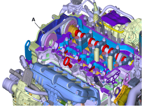
Components and components location
| Components |

| 1. Cylinder head cover 2. Engine oil filler cap 3. Breather hose 4. PCV hose 5. Cylinder head cover gasket | 6. Oil seal 7. Gasket 8. High pressure fuel pump gasket 9. Cam position sensor |
Repair procedures
| Removal |
| 1. | Disconnect the battery negative terminal. |
| 2. | Remove the engine cover (A).
|
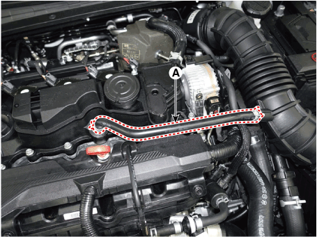
| 3. | Disconnect the breather hoses (A).
|
| 4. | Disconnect the wiring connectors and harness clamps and remove the connector brackets around the cylinder head cover.
|
| 5. | Remove the high pressure fuel pump. (Refer to Engine Control / Fuel System - "High Pressure Fuel Pump") |
| 6. | Remove the ignition coil. (Refer to Engine Electrical System - "Ignition Coil") |
| 7. | Remove the CVVD actuator. (Refer to Engine Control / Fuel System - "CVVD Acuator") |
| 8. | Remove the cylinder head cover (A) with gasket.
|
| Installation |
| 1. | Install the cylinder head cover.
|
| 2. | Install the other parts in the reverse order of removal. |
CVVT & Camshaft
Repair procedures
| Removal |
| 1. | Disconnect the battery negative terminal. |
| 2. | Remove the cylinder head cover. (Refer to Cylinder Head Assembly - "Cylinder Head Cover") |
| 3. | Turn the crankshaft damper pulley so that No. 1 piston is at top dead center.
|
| 4. | Remove the intake and exhaust variable force solenoid (VFS) valves (A).
|
| 5. | Remove the cam to cam guide (A).
|
| 6. | Remove the fuel pump bracket (A).
|
| 7. | Remove the camshaft front bearing cap (A) and camshaft bearing caps (B).
|
| 8. | Loosen the service hole bolt (A).
|
| 9. | Install the jack to the edge of oil pan |
| 10. | Lift the engine using the jack to obtain space. |
| 11. | Release the lock by putting down rachet plate (B) of timing chain tensioner with using back of tiny awl (A).
|
| 12. | Remove the intake oil control valve (OCV) & center bolt (A).
|
| 13. | Remove the exhaust oil control valve (OCV) and center bolt (A).
|
| 14. | Remove the CVVD assembly.
When Using the CVVD fixture
When not using the CVVD fixture
|
| 15. | Remove the Intake CVVT (A).
|
| 16. | Remove the exhaust camshaft (A).
|
| 17. | Remove the exhaust CVVT (A).
|
| Inspection |
Camshaft
| 1. | Measure the height of the cam. Check the surface of the cam lob for wear and tear. If necessary, replace the camshaft.
|
| 2. | Inspect the camshaft journal clearance.
|
| 3. | Inspect the camshaft end play.
|
| Installation |
| 1. | Install the intake CVVT (A).
|
| 2. | Install the CVVD assembly (A).
|
| 3. | Install the intake OCV & center bolt (A).
|
| 4. | Compress the timing chain tensioner piston.
|
| 5. | Install the exhaust CVVT (A).
|
| 6. | Install the exhaust camshaft (A).
|
| 7. | Install the exhaust oil control valve (OCV) and center bolt (A).
|
| 8. | Install the camshaft front bearing cap (A) and camshaft bearing caps (B).
|
| 9. | Remove the fine gimlets (A) that hold the timing chain tensioner.
|
| 10. | When installing the timing chain, be sure that the timing mark (A) of each sprocket is matched with the timing mark (B) (color link) of the timing chain. [Intake CVVT Timing Mark]
[Exhaust CVVT Timing Mark]
|
| 11. | Install the fuel pump bracket (A).
|
| 12. | Install the cam to cam guide (A).
|
| 13. | Install the intake and exhaust variable force solenoid (VFS) valves (A).
|
| 14. | Install the cylinder head cover. (Refer to Cylinder Head Assembly - "Cylinder Head Cover") |
CVVD Assembly
Description and operation
| Description |
CVVD (Continuous Variable Valve Duration) System is a device to control the optimum open and close timing according to the driving mode by changing the valve opening section.
It is composed of cam shaft, CVVD assembly, and CVVD acatuator.
The valve opening time operates in proportion to the rpm of control shaft.

| Operation Principle |
[CVVD System Operating Mode]
| Optimum Valve Timing by Engine Load |

Repair procedures
| Removal |
| 1. | Disconnect the battery negative terminal. |
| 2. | Remove the cylinder head cover. (Refer to Cylinder Head Assembly - "Cylinder Head Cover") |
| 3. | Turn the crankshaft damper pulley so that No. 1 piston is at top dead center.
|
| 4. | Remove the Intake variable force solenoid (VFS) valve (A).
|
| 5. | Remove the cam to cam guide (A).
|
| 6. | Reomve the front bearing cap (A) and intake camshaft bearing caps (B).
|
| 7. | Remove the service hole bolt (A).
|
| 8. | Remove the engine mounting support bracket. (Refer to Engine and Transaxle Assembly - "Engine Mounting") |
| 9. | Lift the engine using the jack to obtain space. |
| 10. | Release the lock by putting down rachet plate (B) of timing chain tensioner with using back of tiny awl (A).
|
| 11. | Remove the intake oil control valve (OCV) & center bolt (A).
|
| 12. | Remove the CVVD assembly.
When Using the CVVD fixture
When not using the CVVD fixture
|
| 13. | Remove the Intake CVVT (A).
|
| Installation |
| 1. | Install the Intake CVVT (A).
|
| 2. | Install the CVVD assembly (A).
|
| 3. | Install the intake OCV & center bolt (A).
|
| 4. | Compress the timing chain tensioner piston.
|
| 5. | Install the front bearing cap and camshaft bearing cap
|
| 6. | Remove the fine gimlets (A) that hold the timing chain tensioner.
|
| 7. | When installing the timing chain, be sure that the timing mark (A) of each sprocket is matched with the timing mark (B) (color link) of the timing chain. [Intake CVVT Timing Mark]
[Exhaust CVVT Timing Mark]
|
| 8. | Install the cam to cam guide (A).
|
| 9. | Install the intake variable force solenoid (VFS) valve (A).
|
| 10. | Install the cylinder head cover. (Refer to Cylinder Head Assembly - "Cylinder Head Cover") |
Cylinder Head
Repair procedures
| Removal |
|
|
| 1. | Disconnect the negative battery terminal.
|
| 2. | Remove the engine cover. (Refer to Engine and Transaxle Assembly - "Engine Cover") |
| 3. | Remove the engine room under cover. (Refer to Engine and Transaxle Assembly - "Engine Room Under Cover") |
| 4. | Drain the coolant. (Refer to Cooling System - "Coolant") |
| 5. | Remove the air duct and air cleaner assembly. (Refer to Intake and Exhaust System - "Air Cleaner") |
| 6. | Remove the battery and battery tray. (Refer to Engine Electrical System - "Battery") |
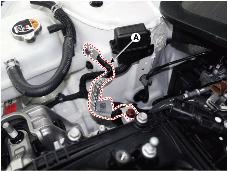
| 7. | Remove the engine ground cable (A).
|
| 8. | Disconnect the radiator upper hose (A).
|
| 9. | Disconnect the coolrant reservoir tank coolant hose (A).
|
| 10. | Disconnect the heater hoses (A).
|
| 11. | Disconnect the brake vacuum hose (A).
|
| 12. | Disconnect the fuel hose (A) and purge control solenoid valve (PCSV) hose (B).
|
| 13. | Remove the intake manifold. (Refer to Intake and Exhaust System - "Intake Manifold") |
| 14. | Remove the delivery pipe. (Refer to Engine Control / Fuel System - "Delivery Pipe") |
| 15. | Remove the exhaust manifold. (Refer to Intake and Exhaust System - "Exhaust Manifold") |
| 16. | Remove the vaccum pump (A).
|
| 17. | Remove the integrated thermal management module (ITM). (Refer to Cooling System - "Integrated Thermal Management Module (ITM)") |
| 18. | Remove the heater pipe mounting bolts (A).
|
| 19. | Remove the spark plug. (Refer to Engine Electrical System - "Spark Plug") |
| 20. | Remove the timing chain. (Refer to Timing System - "Timing Chain") |
| 21. | Remove the camshaft front bearing cap (A) and camshaft bearing caps (B).
|
| 22. | Remove the CVVD assembly (A).
When Using the CVVD fixture
When not using the CVVD fixture
|
| 23. | Remove the exhaust camshaft & CVVT assembly (A).
|
| 24. | Remove the cylinder head heat protector (A).
|
| 25. | Remove the cylinder head degasing water hose and pipe (A).
|
| 26. | Remove the cam carrier (A).
|
| 27. | Remove the hydraulic lash adjuster (HLA) (A) and swing arm (B).
|
| 28. | Remove the cylinder head.
|
| Disassembly |
| 1. | Remove the valves.
|
| Inspection |
| Cylinder Head |
| 1. | Inspect for flatness. Using a precision straight edge and feeler gauge, measure the contacting surface of the cylinder block and the manifolds for warpage.
|
| 2. | Inspect for cracks. Check the combustion chamber, intake ports, exhaust ports and cylinder block surface for cracks. If cracked, replace the cylinder head. |
Valve And Valve Spring
| 1. | Inspect valve stems and valve guides.
|
| 2. | Inspect the valves.
|
| 3. | Inspect the valve seats.
|
| 4. | Inspect the valve springs.
|
| Reassembly |
|
| 1. | Install the valves.
|
| Installation |
|
| 1. | Install the cylinder head.
|
| 2. | Install the new cylinder head bolts.
|
| 3. | Install the hydraulic lash adjuster (HLA) (A) and swing arm (B).
|
| 4. | Install the cam carrier to the cylinder head.
|
| 5. | Install the cylinder head degasing water hose and pipe (A).
|
| 6. | Install the cylinder head heat protector (A).
|
| 7. | Install the exhaust camshaft & CVVT assembly (A).
|
| 8. | Install the CVVD assembly.
|
| 9. | Install the camshaft front bearing cap (A) and camshaft bearing caps (B).
|
| 10. | Install the other parts in the reverse order of removal. |
| 11. | Fill with engine coolant. (Refer to Cooling System - "Coolant")
|
| 12. | Refill engine with engine oil. (Refer to Lubrication System - "Engine Oil") |
Vacuum Pump
Repair procedures
| Removal |
| 1. | Disconnect the battery negative terminal. |
| 2. | Remove the air duct and air cleaner assembly. (Refer to Intake and Exhaust System - "Air Cleaner") |
| 3. | Remove the battery and battery tray. (Refer to Engine Electrical System - "Battery") |
| 4. | Disconnect the brake vacuum hose (A).
|
| 5. | Disconnect the fuel hose (A) and PCSV hose (B).
|
| 6. | Remove the main wiring protector (A) after disconnecting the connector (B).
|
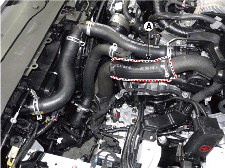
| 7. | Disconnect the intercooler inlet hose (A).
|
| 8. | Remove the intercooler pipe (A).
|
| 9. | Remove the vaccum pump (A).
|
| 10. | Install in the reverse order of removal. |


