 Hyundai Elantra CN7: Clutch System
Clutch Cover And Disc
Repair procedures
| Removal |
| 1. | Remove the manual transaxle assembly. (Refer to Manual Transaxle System - "Manual Transaxle") |
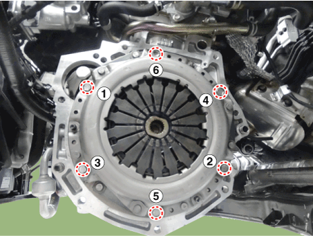
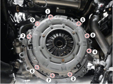
| 2. | Remove the clutch cover assembly after loosening the bolts.
[Gasoline 1.6 MPI / Gasoline 1.6 T-GDI]
[Gasoline 2.0 MPI]
|
| Inspection |
| 1. | Inspect diaphragm spring wear which is in contact with a concentric slave cylinder bearing. |
| 2. | Check the clutch cover and disc surface for wear or cracks. |
| 3. | Check the clutch disc facing for slipping or oil marks. |
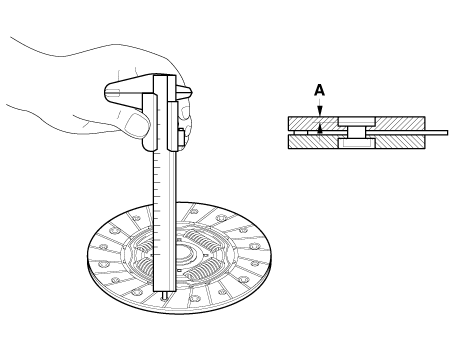
| 4. | Measure the depth from a clutch facing surface to a rivet. If the measured value is less than the specification below, replace it.
|
| Installation |
|
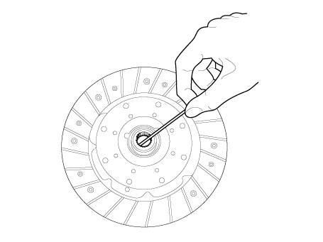
| 1. | Apply grease on a disc spline part and transaxle input shaft spline part as required.
|
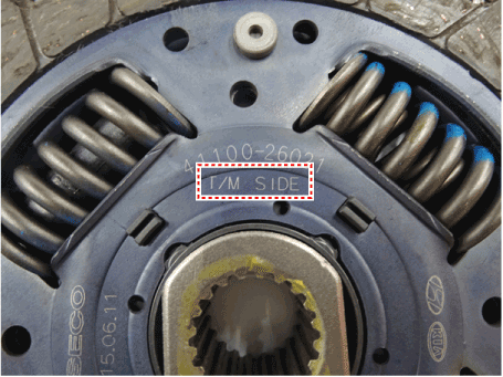
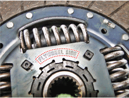
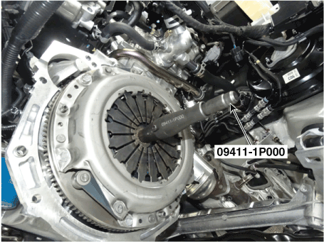
| 2. | Before installing the clutch disc, check the “TM SIDE” and “FLYWHEEL SIDE” marked on the clutch disc, and install it with the clutch cover using a special tool (09411-1P000).
|
| 3. | Install the clutch disc and the cover with SST (A: 09411-1P000).
|
| 4. | Install the clutch cover mounting bolts.
|
| 5. | Remove the clutch disc guide SST (No.: 09411-1P000).
|
| 6. | Install the transaxle assembly. (Refer to Manual Transaxle System - "Manual Transaxle") |
Ignition Lock & Clutch Switch
Description and operation
| Description |
| – | Clutch operation is detected through clutch switch signal. This signal enables ECM to cope with instant change of load condition. |
| – | Clutch switch signal is used to detect engaged gear with vehicle speed and engine speed. |
Schematic diagrams
| Connector and Pin Function |
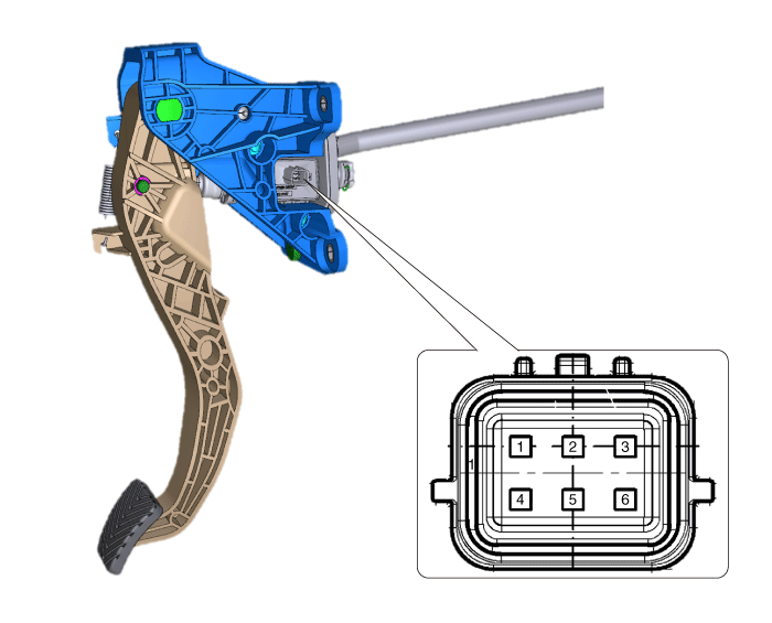
| Connector |
|
Terminal
|
Description
|
| 1 | IG1 |
| 2 | Clutch switch |
| 3 | Ignition lock switch |
| 4 | Battery + |
| 5 | PWM signal |
| 6 | Ground |
Repair procedures
| Replacement |
|
Clutch Pedal
Components and components location
| Components |
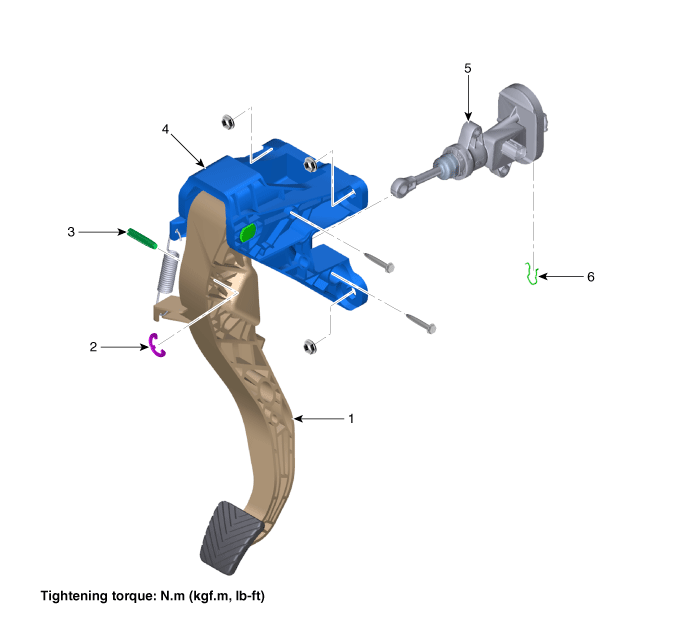
| 1. Clutch pedal arm 2. Clip 3. Push rod pin | 4. Clutch pedal assembly 5. Clutch master cylinder 6. Clip |
Repair procedures
| Removal |
| 1. | Remove the air cleaner assembly and air duct. (Refer to Engine Mechnical System - "Air Cleaner") |
| 2. | Remove the battery and battery tray. (Refer to Engine Electrical System - "Battery") |
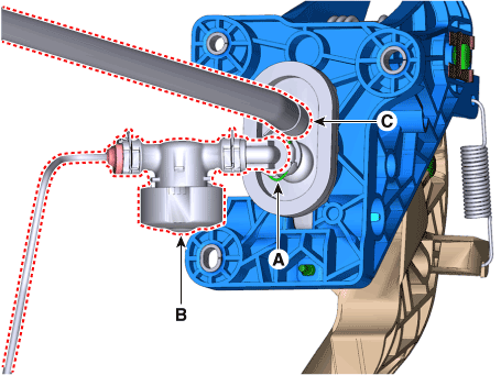
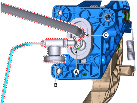
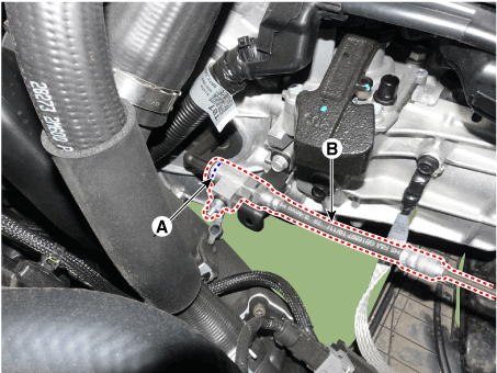
| 3. | Pull the snap pin (A) and then separate the clutch regulator (B). [Gasoline 1.6 MPI / Gasoline 2.0 MPI]
[Gasoline 1.6 T-GDI]
|
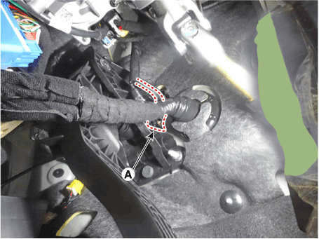
| 4. | Disconnect the ignition lock & clutch switch connector (A).
|
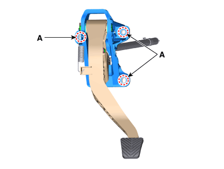
| 5. | Loosen the nuts (A) and then removing the clutch pedal.
|
| Installation |
| 1. | To install, reverse the removal procedures. |
| 2. | Perform bleeding air procedure in concentric slave cylinder after pouring the brake fluid. (Refer to Clutch System - "Concentric Slave Cylinder Assembly") |
Regulator
Components and components location
| Components and Components Location |
| [Gasoline 1.6 MPI / Gasoline 2.0 MPI] |
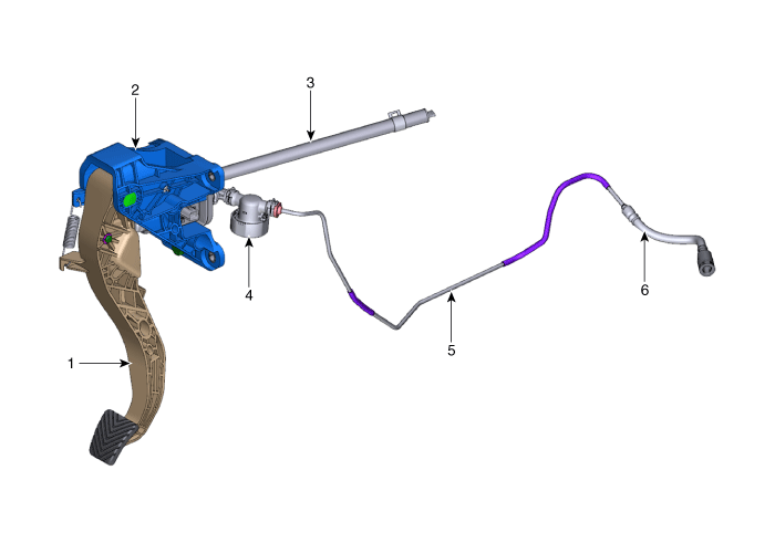
| 1. Clutch pedal arm 2. Clutch pedal assembly 3. Reservoir hose | 4. Regulator 5. Cluch tube 6. Clutch hose |
| [Gasoline 1.6 T-GDI] |
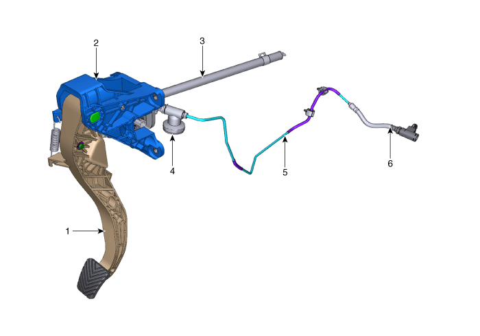
| 1. Clutch pedal arm 2. Clutch pedal assembly 3. Reservoir hose | 4. Regulator 5. Cluch tube 6. Clutch hose |
Repair procedures
| Removal |
| 1. | Remove the air duct and air cleaner assembly. (Refer to Engine Mechanical System - "Air Cleaner") |
| 2. | Remove the battery and battery tray. (Refer to Engine Electrical System - "Battery") |
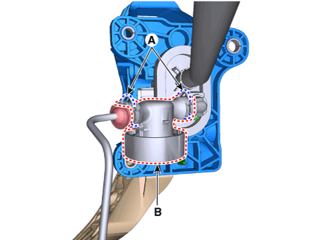
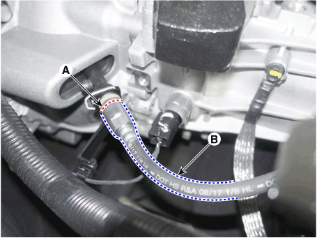
| 3. | Pull the snap pins (A) and then removing the regulator (B). [Gasoline 1.6 MPI / Gasoline 2.0 MPI]
|
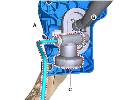
| 4. | Pull the snap pin (B) after separate the clutch tube (A) and Remove the regulator (C). [Gasoline 1.6 T-GDI]
|
| Installation |
| 1. | To install, reverse the removal procedures.
|
| 2. | After be equipped, perform bleeding air procedure in concentric slave cylinder after pouring the brake fluid. (Refer to Clutch System - "Concentric Slave Cyilnder Assembly") |
| Inspection |
| 1. | Check the clutch tube for fluid leakage. |
| 2. | Check the clutch tube for strain and damage. |
Clutch Tube
Components and components location
| Components and Components Location |
| [Gasoline 1.6 MPI / Gasoline 2.0 MPI] |

| 1. Clutch pedal arm 2. Clutch pedal assembly 3. Reservoir hose | 4. Regulator 5. Cluch tube 6. Clutch hose |
| [Gasoline 1.6 T-GDI] |

| 1. Clutch pedal arm 2. Clutch pedal assembly 3. Reservoir hose | 4. Regulator 5. Cluch tube 6. Clutch hose |
Repair procedures
| Removal |
| 1. | Remove the air cleaner and air duct. (Refer to Engine Mechanical System - "Air Cleaner") |
| 2. | Remove the battery and battery tray. (Refer to Engine Electrical System - "Battery") |
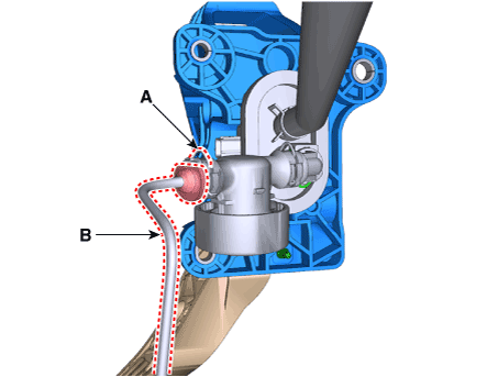
| 3. | Pull the snap pin (A) and then separate the clutch tube (B). [Gasoline 1.6 MPI / Gasoline 2.0 MPI]
|
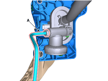
| 4. | Loosen the flare nut and then separate the clutch tube (A). [Gasoline 1.6 T-GDI]
|
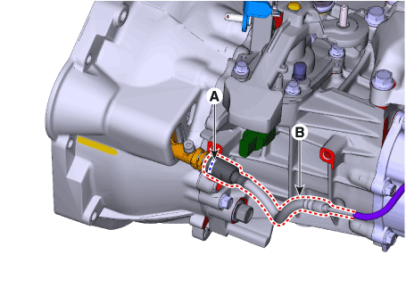
| 5. | Remove the snap pin (A) and then separate the clutch hose & tube (B). [Gasoline 1.6 MPI]
[Gasoline 1.6 T-GDI]
[Gasoline 2.0 MPI]
|
| 6. | Remove the clutch hose & tube from the vehicle. |
| Installation |
| 1. | To install, reverse the removal procedures. |
| 2. | Perform bleeding air procedure in concecntric slave cylinder after pouring the brake fluid (Refer to Clutch System - "Concentric Slave Cylinder Assembly") |
Clutch Master Cylinder
Components and components location
| Components |

| 1. Clutch pedal arm 2. Clip 3. Push rod pin | 4. Clutch pedal assembly 5. Clutch master cylinder 6. Clip |
Repair procedures
| Removal |
| 1. | Remove the clutch pedal. (Refer to Clutch System - "Clutch Pedal") |
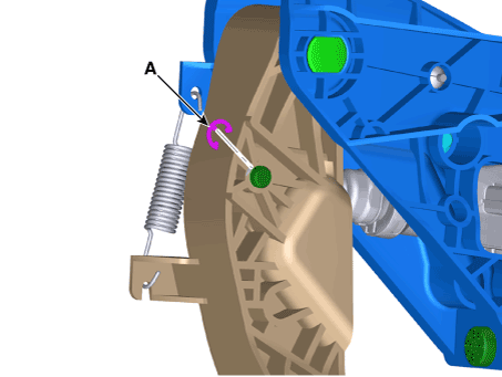
| 2. | Remove the clip (A).
|
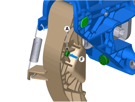
| 3. | Remove the push rod pin (A) by pushing it in the “F” direction.
|
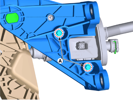
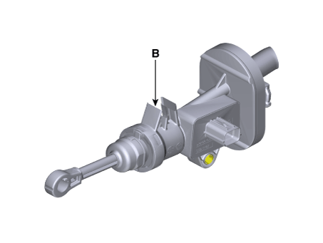
| 4. | Loosen the bolts (A) and then removing the clutch master cylinder (B).
|
| Installation |
| 1. | To install, reverse the removal procedures. |
| 2. | Perform bleeding air procedure in concecntric slave cylinder after pouring the brake fluid. (Refer to Clutch System - "Concentric Slave Cylinder Assembly") |
Concentric Slave Cylinder Assembly
Repair procedures
| Removal |
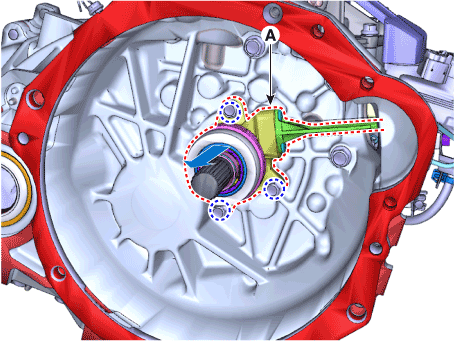
| 1. | Remove the manual transaxle assembly. (Refer to Manual Transaxle System - "Manual Transaxle") |
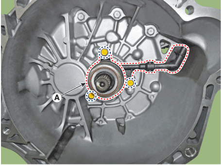
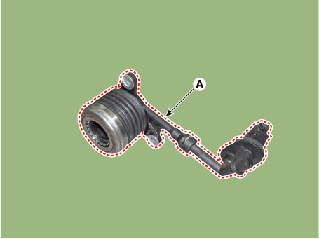
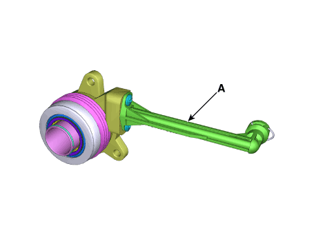
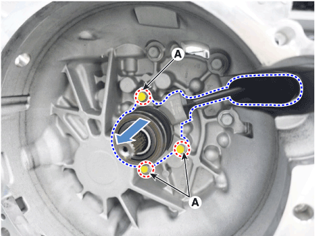
| 2. | Loosen the bolts and then removing the concentric slave cylinder assembly (A) from the clutch housing. [Gasoline 1.6 MPI]
|
| 3. | Loosen the bolts and then removing the concentric slave cylinder assembly (A) from the clutch housing. [Gasoline 1.6 T-GDI]
|
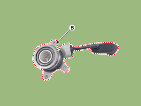
| 4. | Remove the concentric slave cylinder assembly (B) from the transaxle case by removing bolts (A). [Gasoline 2.0 MPI]
|
| Installation |
| 1. | To install, reverse the removal procedures.
|
| 2. | Perform bleeding air procedure in concecntric slave cylinder after pouring the brake fluid. (Refer to Concentric Slave Cylinder Assembly - "Adjustment") |
| Adjustment |
| Air Bleeding Procedure [Gasoline 1.6 MPI] |
| 1. | Turn ignition switch OFF and disconnect the negative (-) battery cable. |
| 2. | Remove the air cleaner assembly and air duct. (Refer to Engine Mechanical System - "Air Cleaner") |
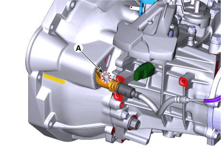
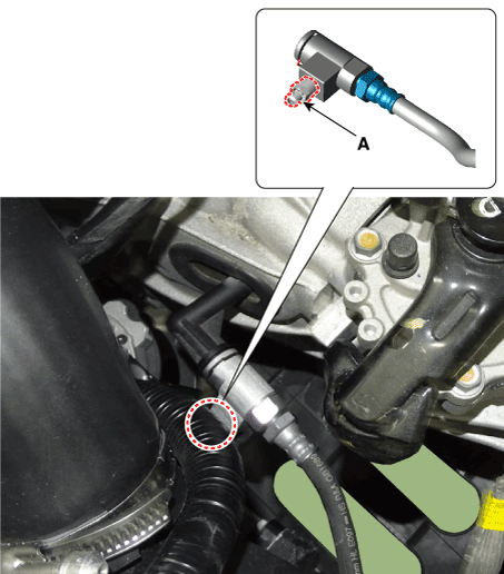
| 3. | Open the concentric slave cylinder air bleed cap (A).
|
| 4. | Connect the vinyl hose to the air bleeder plug (A).
|
| 5. | Pull the clip and then moving the clutch hose towards the arrow direction.
|
Air Bleeding Procedure [Gasoline 1.6 T-GDI]
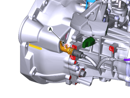
| 1. | After disconnecting a cap from the concentric slave cylinder air bleeder, insert a vinyl hose in the plug. |
| 2. | Refill the reservoir tank with the specified fluid.
|
| 3. | Pump the clutch pedal about 10 times. |
| 4. | Loosen the air bleed screw (A) at hold down the clutch pedal to allow air to escape from the clutch system. Then tighten the air bleed screw.
|
| 5. | Repeat the step 2 - 4 until there is no bubble in the fluid. |
Air Bleeding Procedure [Gasoline 2.0 MPI]
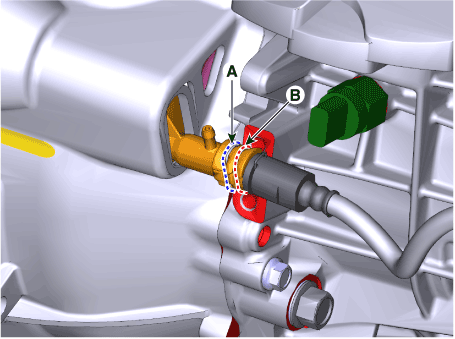
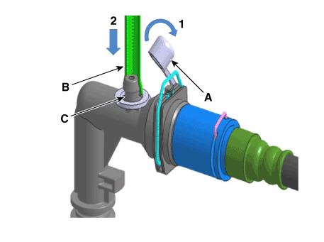
| 1. | Open the Concentric Slave Cylinder (CSC)'s cap (A) and connect the hose (B) to the CSC's plug (C).
|
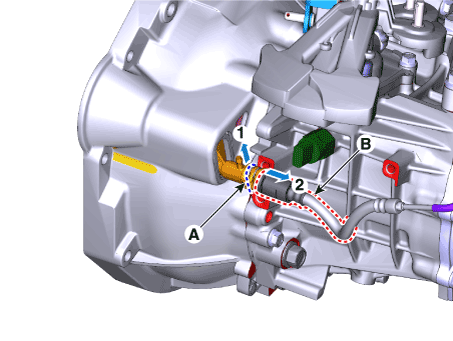
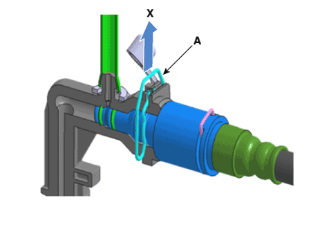
| 2. | Pull the connector (B) towards the arrow direction while pressing the CSC's double clip (A). |
| 3. | Move about 5 mm(0.1969in.) until you feel the click.
|
| 4. | Fill the vehicle's reservoir tank with specified oil.
|
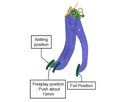
| 5. | Repeatedly depress the clutch pedal (A) to the full position until the bubble is not discharged from the hose. (Fill the reservoir tank with the oil if necessary.)
|
| 6. | When the air bleeding is completed, maintain the clutch pedal (A) in full position and push the connector (B) until you hear the "click" sound and restore to the initial position.
|
| 7. | For little air bleeding of Concentric Slave Cylinder (CSC)-Clutch Master Cylinder(CMC) area, maintain the clutch pedal (A) in freeplay position and push the double clip (B), In this case, the connector (C) is moved about 5 mm(0.1969in.) towards the arrow direction.
|
| 8. | Check for bubble by depressing the clutch pedal from the freeplay to the full position.
|
| 9. | When the air bleeding is completed, maintain the clutch pedal (A) in full position and push the connector (B) until you hear the "click" sound and restore to the initial position.
|
| 10. | Remove the hose and close the cap (A) if there is no bubble.
|


