Specifications
Items
|
Specification
|
Rated voltage
|
DC 12V
|
Operating voltage
|
9V ~ 16V
|
Operating speed
|
30?/h ~ 225?/h
|
Sensible distance
|
30m (Sedan)
|
Curvature radius
|
Start : More than 100m/30km/h
Stop : Less than 70m
|
Frequency
|
24 GHz
|
Numbers
|
2EA (Master 1EA, Slave 1EA)
|
Components and Components Location
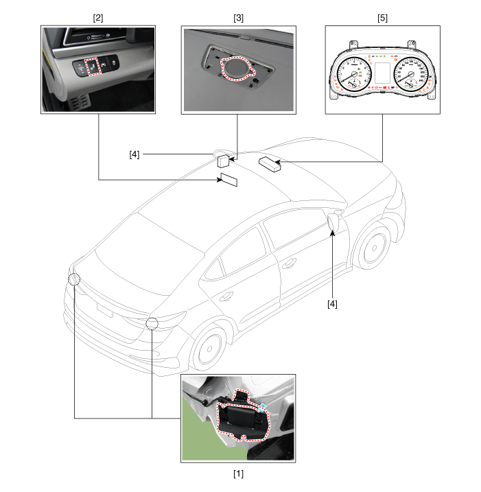
1. Blind Spot Detection (BSD) Unit
2. BSD switch
3. Speaker
|
4. BSD warning lamp
5. Cluster
|
Description and Operation
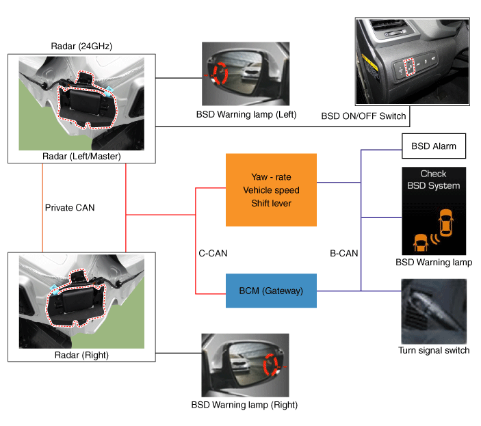
BSD is a system that uses two magnetic wave radar sensors attached on the rear panel
to measure the distance from the following vehicles and provides the sensing and
(visual and auditory) alarm of any vehicle coming into the blind spot.
| - |
Blind Spot Detection (BSD) :
Senses other vehicles in the BSD zone and the display a BSD warning lamp
on the sied mirror for the driver. Warning lamp is blink ON when driver
turns on the turn signal lamp to enter the lane where another vehicle is.
|
| - |
Lane Change Assist (LCA) : Senses
other high-speed access vehicles in the LCA zone and the display a BSD warning
lamp on the sied mirror for the driver. Warning lamp is blink ON when
driver turns on the turn signal lamp without recognizing any sudden approaching
vehicle from that direction.
|
| - |
Rear Cross Traffic Alert (RCTA)
: It generates the alarming to the vehicle approaching from the rear and
side during driving the vehicle backwards. |
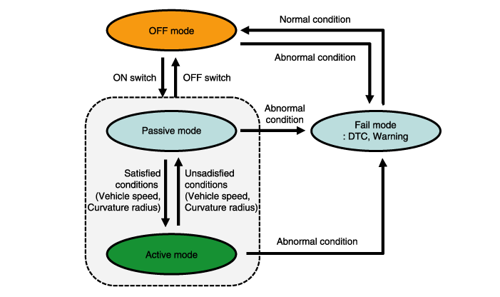
System Operating Mode
| 1. |
When starting the engine with
the switch off, OFF mode is on. |
| 2. |
When pressing ON switch in OFF
mode, Passive mode is on. |
| 3. |
If starting the engine with the
switch ON, Passive mode is on. ? When IGN is ON, the switch is in the
initial state : The last position is kept.
| A. |
If IGN OFF > ON with
the switch ON, the switch is ON. |
| B. |
If IGN OFF > ON with
the switch OFF, the switch is OFF. |
|
| 4. |
If you start the engine with
BSD switch ON, or if you turn on BSD with BSD switch OFF, the warning lamp
of the door mirror flickers for 2 to 3 seconds. This is to inform the
driver that the BSD system is ready. (provided that if the system is in
Fail mode, there is no flickering.)
|
| 5. |
If the activation conditions
(speed and curvature radius) are met while driving, Active mode is on (warning
issued). |
| 6. |
If the activation conditions
(speed and curvature radius) are not met while driving, Passive mode is
on (warning removed). |
| 7. |
If BSD & LCA operation fails
in any mode, Fail mode is on. |
| 8. |
If BSD & LCA operation operates
normally in Fail mode, OFF mode is on. |
| 9. |
If pressing OFF switch while
BSD & LCA function is operating (Active/Passive), OFF mode is on. |
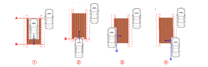
Warning Condition
| 1. |
Warning zone
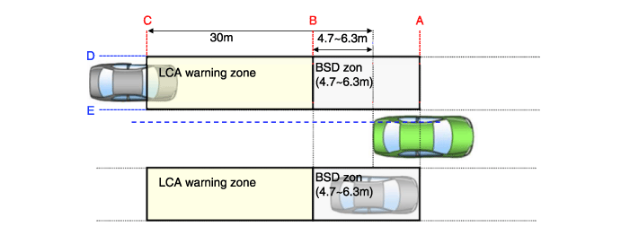
|
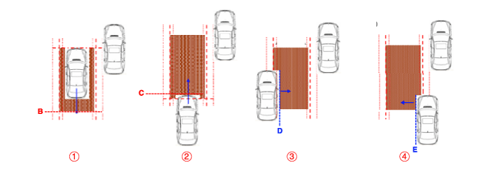
| 4. |
Conditions for LCA warning ON
 The entire body of the target vehicle is located
behind the line 2.5. The entire body of the target vehicle is located
behind the line 2.5.
 Any part of the target vehicle pass the line
C. Any part of the target vehicle pass the line
C. Any part of the target vehicle passes the
line D and Hysteresis In. Any part of the target vehicle passes the
line D and Hysteresis In.
 The entire part of the target vehicle passes
the line E and Hysteresis In. The entire part of the target vehicle passes
the line E and Hysteresis In. In the all above
condition, TTC(Time to Collision) is not less than 2.5 sec. In the all above
condition, TTC(Time to Collision) is not less than 2.5 sec.
|
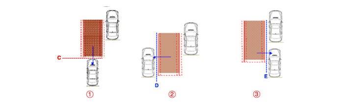
| 5. |
Conditions for LCA warning OFF
The entire body of the target vehicle is located
before the line B.
The entire body of the target vehicle pass
the line C. The entire body of the target vehicle
passes the line D and Hysteresis Out.
The entire body of the target vehicle passes
the line E and Hysteresis Out. In the all above
condition, TTC(Time to Collision) is not more than 2.5 sec.
|
| 6. |
Sensor activation conditions
BSD & LCA switch (indicated by the switch
LED) is on.
Vehicle Speed : 30 km/h or faster
Curvature radius : 100m or more
Relative car speed : -10 ~ 255?/h("-" means
overtaking the preceding vehicle)
|
| 7. |
Sensor deactivation conditions
BSD & LCA switch (indicated by the switch LED)
is off.
Vehicle Speed : 28 km/h or slower
Curvature radius : 125m or less
Relative car speed : All except -10 ~ 255?/h
("-" means overtaking the preceding vehicle)
|
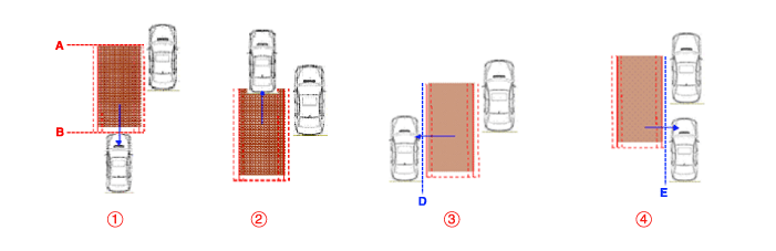
| 9. |
Rear Cross Traffic Alert (RCTA)
Item
|
Specification
|
Remarks
|
Vehicle speed
|
0 ~ -10 kph
|
R' position
|
Time To Collision
|
4 ~ 36 kph
|
+ : closing
|
Operating area
|
0.5 ~ 20 m
|
Vehicle : 20m
Bike : 15m
|
It is a function for helping to check the
vehicle approaching from the rear and side when the car is started to backwards
from parking to the front in the parking lot.
The alarming is made for the vehicle within
2 seconds based on the Time To Collision (TTC) and the human is excluded
for alarming (The alarming may not be made.)
| •
|
Time To Collision
(TTC) : It means to alarm in case of 2~3.5 seconds for estimated
time to colliding through calculating the relative distance/relative
velocity. (It is changed depending on the relative speed
of approaching.) |
|
Warning zone
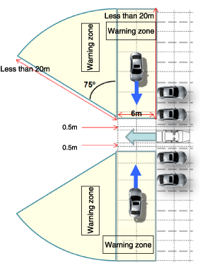
|
Repair procedures
| 1. |
BSD system defects can be quickly
diagnosed with the GDS. GDS operates actuator quickly to monitor, input/output
value and self diagnosis. |
| 2. |
Connect the cable of GDS to the
data link connector in driver side crash pad lower panel, turn the power
on GDS. |
| 3. |
Select the vehicle model and
then BSD system. |
| 4. |
Select "Input/output monitoring",
if you want to check current data of BSD system.

|
| 5. |
If you want to check each module
operation forcefully, select "Actuation test".
|
| 6. |
Ignition "OFF", connect GDS.
|
| 7. |
Ignition "ON” & Engine "OFF",
select BSD system and "BSD Radar Calibration" mode.
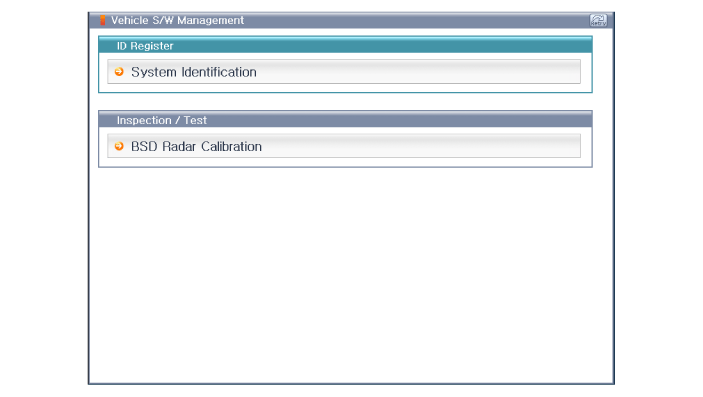
|
| 8. |
The GDS will show the BSD Reset
function steps.
| (1) |
Erase BSD diagnostic
codes. |
| (2) |
BSD initialization.
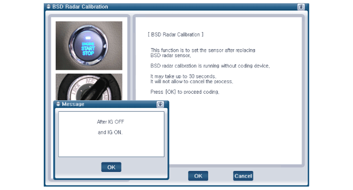
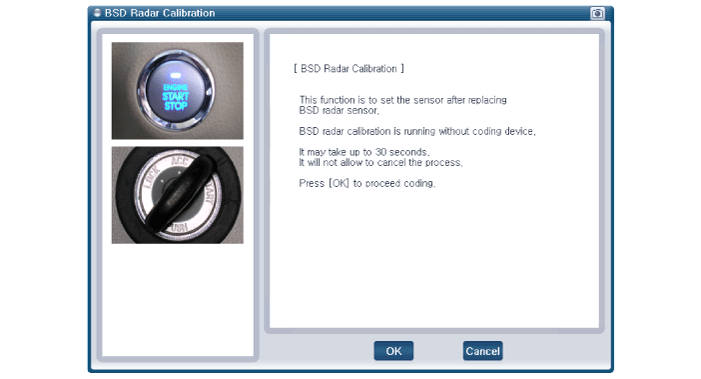
|
|
| 9. |
The BSD initialization procedure
will be performed.
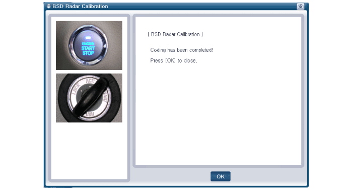
|
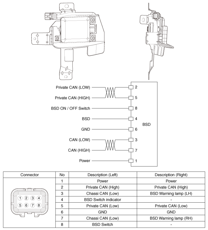
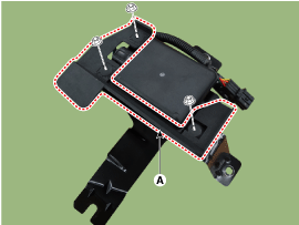
Blind Spot Detection Unit Schematic Diagrams
Blind Spot Detection Unit Repair procedures
| 1. |
Disconnect the negative (-) battery
terminal. |
| 2. |
Remove the rear bumper. (Refer
to Body - "Rear Bumper")
|
| 3. |
Remove the BSD unit (A) after
loosening the mounting nuts.
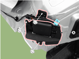
| •
|
Take care not
to separate the bracket from rear bumper when removing the
BSD sensor. |
|
|
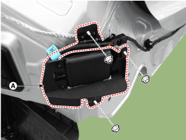
| 1. |
Install the BSD units to the
rear bumper. |
| 2. |
Install the rear bumper. |
| 3. |
Connect the negative (-) battery
terminal.
| •
|
Take care not
to confuse left side (master) and right side (slave) unit
when installing. |
| •
|
BSD units connector
connect to the wiring connector. |
|
|
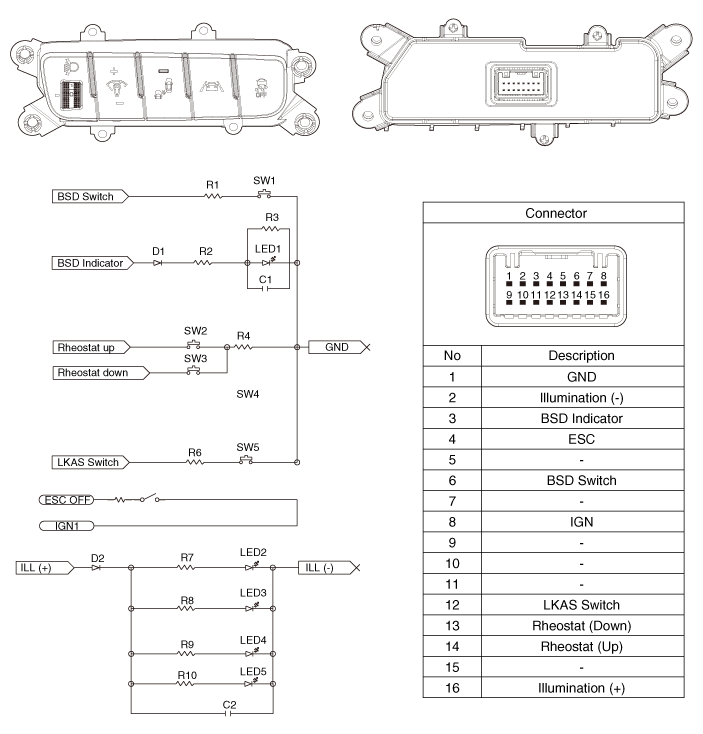
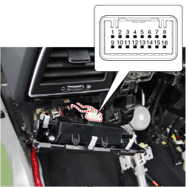
Blind Spot Detection Switch Components and Components Location
Blind Spot Detection Switch Repair procedures
| 1. |
Disconnect the negative (-) battery
terminal. |
| 2. |
Remove the crash pad lower panel.
(Refer to Body - "Crash Pad Lower Panel")
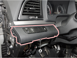
|
| 3. |
Remove the lower crash pad switch
assembly (A) after disengaging the mounting clip.
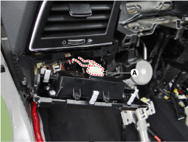
|
| 4. |
Remove the rheostat switch connector
(A).
|
| 5. |
Check for intensity of new rheostat
switch. If the light intensity of the lamps changes smoothly without any
flickering when the rheostat is turned, it can be assumed that the rheostat
is normal.
|
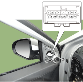
Blind Spot Detection Indicator Components and Components Location
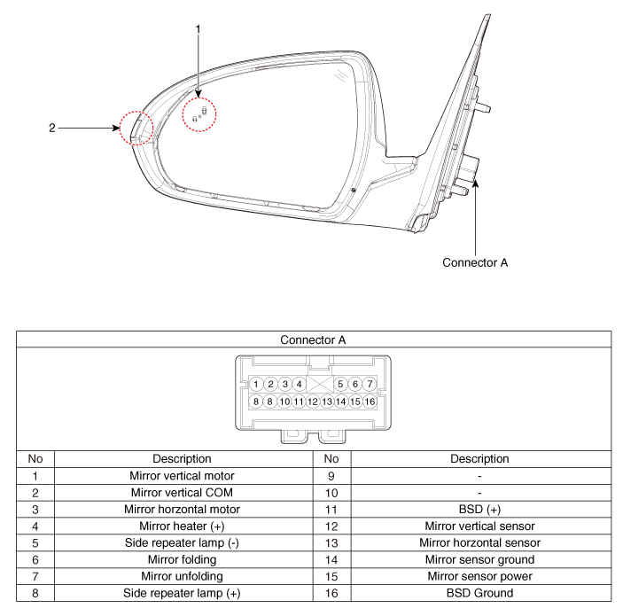
1. BSD Indicator
|
2. Side repeater lamp
|
Blind Spot Detection Indicator Repair procedures
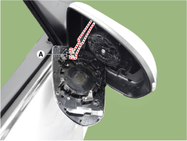
Blind Spot Detection Warnig Indicator
| 1. |
Disconnect the negative (-) battery
terminal. |
| 2. |
Remove the mirror (A).
|
Blind Spot Detection Warnig Indicator
| 1. |
Install the outside mirror. |
| 2. |
Connect the negative (-) battery
terminal. |
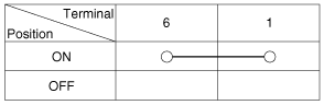
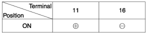
| 1. |
Apply battery voltage to each
terminal as shown in the table and verify that the mirror operates properly.
|
Components and Components Location
Components
1. LKAS ON/OFF Switch
2. Instrument Cluster
3. LKAS Unit
Description and Operation
Descript ...
Schematic Diagrams
Circuit Diaram
Description and Operation
Description
The immobilizer system will disable the vehicle unless the proper ignition key is
used, ...
 Hyundai Elantra AD: Blind Spot Detection System